
High sensitivity alarm

The high-sensitivity alarm circuit is designed to detect changes in ambient light levels, utilizing a light-dependent resistor (LDR) as the primary sensing element. The LDR's resistance decreases with increasing light intensity, allowing the circuit to respond to varying light conditions effectively. The three resistors in the circuit are configured to create a voltage divider, which helps establish the reference voltage levels required for the comparator operation.
The self-excited oscillator generates a square wave signal, which is instrumental in driving the dual-contact switches. This switching action allows the capacitors to charge and discharge at a controlled rate, ensuring that the circuit can sample the voltage levels accurately. The operational amplifier configured as a comparator plays a critical role in determining when the circuit should trigger an alarm. By comparing the voltages at its inverting and non-inverting inputs, the comparator can detect significant changes in light levels.
The sample-and-hold functionality of the circuit allows it to maintain the last sampled voltage during periods of low light fluctuation, ensuring that the alarm remains stable and responsive only to significant changes in light conditions. The monostable multivibrator, triggered by the comparator's output, generates a single pulse of a specified duration, which can be used to activate the relay. The relay serves as the output mechanism to sound an alarm or activate other devices in response to the detected light changes.
Overall, this circuit design is effective for applications requiring high sensitivity to light changes, such as security systems, automatic lighting controls, or environmental monitoring systems. The careful selection of components and their configuration ensures reliable performance and responsiveness to light variations. As shown in the simplified block diagram of the high sensitivity of the alarm circuit, wherein the photoresistor LDR and three ordinary resistor connected. Thus, when the light is at full dark to light changes between full from the potential diagram X point range of about 1/4 to 3/4 of the supply voltage. This potential is applied to the input terminal while the two dual-contact switches. A self-excited oscillator and an inverter circuit controls a combination of these two switches alternately switching, typically a few Hz switching frequency, so that the two capacitors are alternately charged.
As the double-contact switch in the off state its resistance is large, and the comparator constituted by the operational amplifier input impedance is also high. And the capacitor charge storage capacitor between the double contact switch and the comparator plates.
Therefore, when the transfer switch, the discharge rarely. This constitutes a sample and hold circuit. When the charge (potential) capacitor comparator inverting input terminal (-) when the potential rises above the inverting input terminal (+) potential, or when non-inverting input terminal potential lower than the potential of the inverting input terminal, the comparator output becomes low, using the low to trigger followed by a single stable and relay.
Related Circuits
Locker Guard Circuit Diagram. This compact circuit is designed to protect a locker or almirah from burglary. If the locker is opened while in the armed state, the circuit triggers a loud police siren to deter the burglary attempt. The...
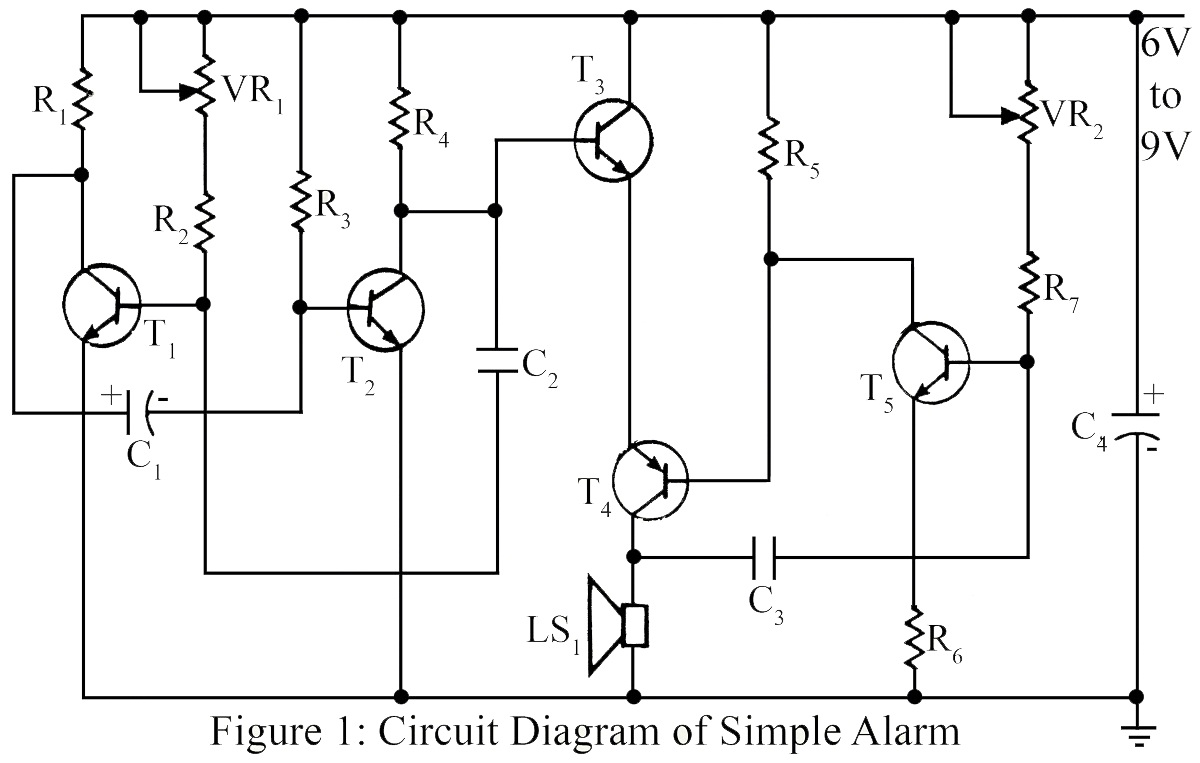
The simple circuit generates an audible alarm notification, functioning as a burglar alarm utilizing five transistors. This circuit operates as a basic burglar alarm system designed to emit an audible sound when triggered. The core component of the circuit is...
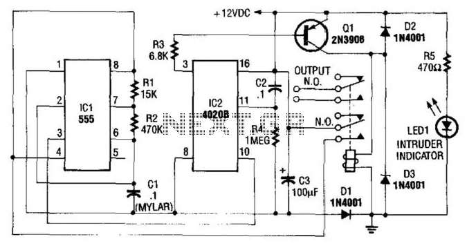
This circuit utilizes a NE555 timer and a CD4020B. When +12 Vdc is applied to the circuit, the output of IC2 is set low via C2, which activates the relay and IC1, functioning as a pulse generator. IC1 generates...
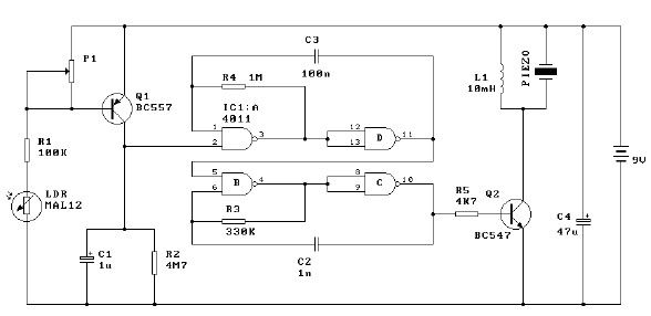
This light alarm schematic circuit is designed using common electronic components, as illustrated in the circuit diagram below. The light alarm circuit will activate an alarm as soon as the drawer is opened and light falls on the Darlington...
This circuit is designed to detect whether the load of a battery charger or plug-in adapter is properly connected. The load may consist of a set of batteries needing charging or any other device that operates on low DC...
Need more current? If you have a larger motor ready for use, the Pololu High Current Motor Driver Board 14A 6V-16V is the ideal solution. Connect three digital lines to your microcontroller (five if error condition feedback is desired),...