
NE555 IC For Infrared Motion Sensor

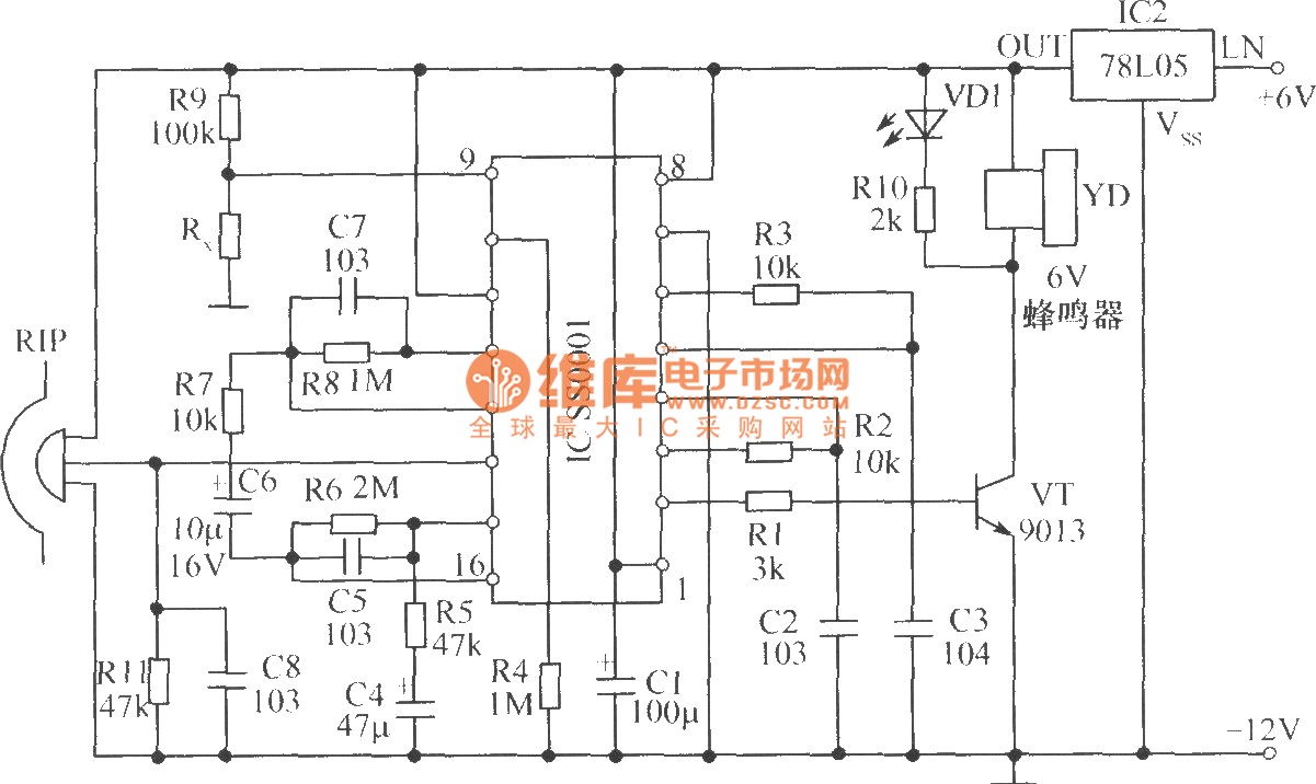
The Infrared Motion Sensor circuit utilizes the NE555 timer IC configured in a monostable mode to detect motion within a specified range. The primary components of the circuit include the NE555 timer, infrared emitter and detector pairs, resistors, capacitors, and a power supply.
In operation, the infrared emitter continuously emits infrared light, which is reflected by objects within the detection zone. When an object moves within the 80-degree coverage area, the reflected infrared light is detected by the infrared receiver. This change in light intensity is interpreted by the NE555 timer, triggering a response.
The timer's output can be connected to various devices such as alarms, lights, or other electronic systems to indicate the presence of motion. The duration of the output pulse can be adjusted by changing the values of the timing components (resistors and capacitors) connected to the NE555, allowing for flexibility in the response time of the circuit.
Overall, this circuit is suitable for applications in security systems, automatic lighting, and other scenarios where motion detection is required. Proper placement of the infrared emitter and detector is crucial to maximize the effectiveness of the detection zone.The following circuit shows about Infrared Motion Sensorcircuit diagram. Features: With NE555 IC, The detection zone coverage is 80 degrees .. 🔗 External reference
Related Circuits
The human infrared thermal release alarm can detect the infrared radiation emitted by the human body at any time of the day or night, triggering both sound and light alarms. This device is particularly suitable for electronic security applications....
This circuit explains alternate wireless switching using an ultrasonic sensor. The distance of the switching range should be more than 10 meters. The described circuit employs an ultrasonic sensor to facilitate wireless switching, allowing for the activation or deactivation of...
This is a sequence timer diagram composed of an NE555 timer. The timer can be set to any duration when the power is connected, allowing it to control an external system. In the circuit, K1-K3 are relays used to...
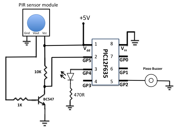
A diode is used in series to drop the voltage to 5.4 V, as the operating voltage for the PIC microcontroller should be below 5.5 V. Additionally, the diode provides protection to the circuit in case of reverse polarity...

A differential temperature sensor is employed to measure the temperature difference between two distinct areas. The schematic diagram of the circuit is provided for reference. The differential temperature sensor circuit typically consists of two temperature sensing elements, such as thermocouples...
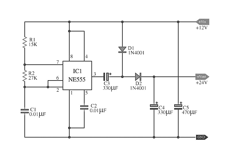
The capacitors C5 work in conjunction with IC1, while the resistors R1 and R2, along with capacitors C1, form an astable multivibrator square wave generator. This generator outputs a frequency of approximately 2 kHz from pin 3 of IC1....