
pic16f877 based digital clock using lcd display codeproteus simulation

The PIC16F877 microcontroller is a versatile and widely used component in embedded systems, particularly suitable for projects like digital clocks. Implementing a digital clock using this microcontroller involves several key components and steps.
The design typically includes a real-time clock (RTC) module or timer to keep track of the current time. The microcontroller interfaces with the RTC to retrieve time data, which is then processed and displayed. The circuit may also incorporate a 7-segment display for visual representation of the time, as well as buttons for setting the time and adjusting the alarm features.
The schematic would generally include the following essential components:
1. **Microcontroller (PIC16F877)**: Acts as the central processing unit, executing the program that controls the clock functions.
2. **Real-Time Clock (RTC) Module**: Often an external component like the DS1307 or DS3231, this module provides accurate timekeeping and communicates with the PIC via I2C protocol.
3. **7-Segment Display**: This display is used to show the hours and minutes. Multiple 7-segment displays may be multiplexed to show the complete time.
4. **Buttons**: Typically, at least two buttons are used for setting the time and toggling between different modes (e.g., time display, alarm setting).
5. **Power Supply**: A stable power source, such as a 5V DC supply, is necessary to power the microcontroller and associated components.
6. **Resistors and Capacitors**: These components are used for current limiting, debouncing switches, and filtering power supply noise.
The programming of the PIC16F877 involves using an integrated development environment (IDE) such as MPLAB X, where the code is written in C or assembly language. The program should handle time increments, display updates, and user input for setting the clock.
In summary, implementing a digital clock with the PIC16F877 microcontroller involves careful selection of components, circuit design, and software programming to ensure accurate timekeeping and user-friendly operation. The use of simulation software like Proteus can aid in visualizing the circuit and debugging the code before physical implementation.This PIC16F877 microcontroller tutorial answers the question, "" How to implement a digital clock using PIC16F877 ? "" Using PIC16 simulator (Proteus) you ca.. 🔗 External reference
Related Circuits
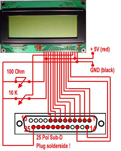
For the wiring of the display, the ribbon cable is first taken and soldered according to the circuit diagram on the 25-pin sub-D (parallel port) plug. The small circuit diagram illustrates the rear side, which is the solder side...
The diagram illustrates a block diagram for an agenda alarm and agenda thermometer system. It includes one temperature sensor, a real-time clock (RTC), a microcontroller (PIC), an EEPROM, a 7-segment display, and a keyboard. The EEPROM is utilized to...
A switch is an electrical component that can break an electrical circuit, interrupting the current or diverting it from one conductor to another. A switch may be directly manipulated by a human as a control signal to a system...
This circuit provides a digital square wave that can be viewed directly or used to drive other circuits. It used the CMOS 4047 Low-Power Monostable/Astable Multivibrator. As used in Tom Duncan's Adventures with Digital Electronics Book, to drive CMOS...
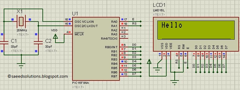
This post presents the LCD interfacing code utilizing the PIC16F84A microcontroller. The code is developed in the C programming language using MPLAB with the HI-TECH C compiler. The interfacing of an LCD (Liquid Crystal Display) with the PIC16F84A microcontroller...
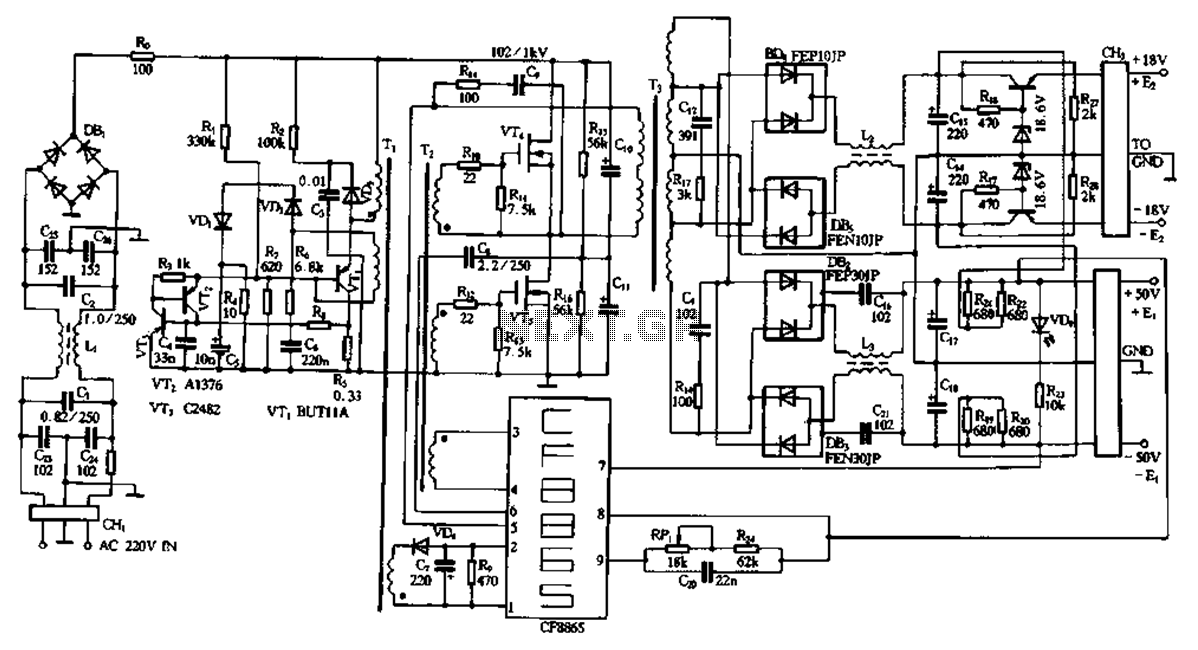
This document describes a specific module utilizing the CF8865 switching power supply circuit, which employs the integrated control module CF8865. In the figure, transistors VT4 and VTs are controlled by the excitation transformer Tz. The output is processed through...