
Infrared receiver by LM1458-CD40103

This project involves the design of a programmable circuit that responds to an input pulse signal. The primary function of the circuit is to activate specific features based on the characteristics of the input signal. The circuit can be configured to perform various tasks depending on the programmed logic.
The core component of the circuit is a microcontroller, which serves as the brain of the operation. The microcontroller is programmed to recognize the input pulse signal and execute predefined actions. For instance, if the input pulse meets certain criteria, the microcontroller can trigger outputs such as LEDs, motors, or other devices.
To implement this circuit, the following components are typically required:
1. **Microcontroller**: A suitable microcontroller, such as an Arduino or PIC, which can be programmed using an integrated development environment (IDE).
2. **Input Signal Source**: This could be a switch, a sensor, or any device capable of generating a pulse signal.
3. **Output Devices**: Depending on the application, these could include LEDs, relays, or other actuators that the circuit will control.
4. **Power Supply**: A stable power source is necessary to power the microcontroller and the connected components.
5. **Resistors and Capacitors**: These passive components may be used for signal conditioning and to ensure stable operation of the circuit.
The circuit layout should include proper connections between the microcontroller, input signal source, and output devices. The input pin of the microcontroller should be connected to the output of the signal source, and the output pins should be connected to the respective output devices. Additionally, pull-up or pull-down resistors may be employed to ensure reliable signal detection.
The programming of the microcontroller must include logic to handle the input signal appropriately, such as debouncing for mechanical switches or pulse width modulation for controlling output devices. The program should also include conditions for activating the output based on the characteristics of the input pulse, enabling the circuit to exhibit the desired special features.
Overall, this project exemplifies the versatility of programmable circuits and their ability to respond dynamically to input signals, making them suitable for a wide range of applications in automation, control systems, and interactive projects.From This simple projects If you want circuits with special features,can be set the program to the circuit works, when the input pluse signal is entered of.. 🔗 External reference
Related Circuits
Flying hand launch gliders necessitate the use of small-capacity receiver NiCad battery packs. While these lightweight packs are advantageous, they have the significant drawback of quickly depleting. Although careful timing of flights can be employed, it often results in...
The induction receiver described is highly sensitive and versatile, suitable for various applications including tracing wiring behind walls, receiving audio from an induction transmitter, detecting lightning and other electrical discharges, and monitoring devices that produce an audio magnetic field,...
This is an infrared gate with two sensors planned to use in the wall in the way behind a door. It can be applied in a toilet to keep track of that someone is inside exceeding a certain amount...
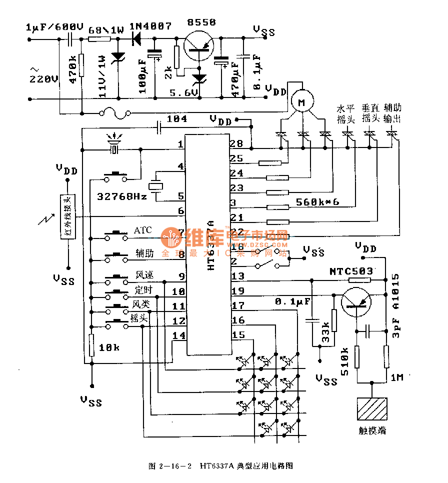
The HT6337 is an infrared remote control receiving decoder circuit specifically designed for electric fan applications. It is housed in a 28-pin dual-row DIP package, with the compatible model being HT12C. The HT6337 is part of a series of...
This compact receiver is slightly larger than an AA battery. It is powered by two LR44 button cells, which are relatively costly and may not have a long lifespan. There is an intention to search for LR44 batteries at...
A simple device designed for quickly checking common infrared remote controls can be beneficial for electronics enthusiasts who often need to repair or test these widespread devices. A reliable circuit was created using a few components: the LED will...