
Infrared Remote Tester

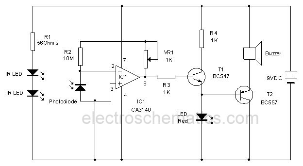
The infrared remote control tester circuit is designed to provide a straightforward method for verifying the functionality of remote controls. The core components include a photo transistor, an LED, and a few passive components such as resistors. When a button on the remote control is pressed, infrared light is emitted from the remote's IR LED. This emitted light is detected by the photo transistor (Q1), which is sensitive to infrared wavelengths.
The circuit operates by converting the infrared light signal into an electrical signal that activates the LED indicator. When the photo transistor receives sufficient infrared light, it allows current to flow, turning on the LED. The flashing of the LED serves as a visual indication that the remote control is functioning properly.
The design emphasizes simplicity and low power consumption, making it ideal for quick checks without the need for complex equipment. With a current draw of less than 1 mA during operation, the circuit is efficient and can be powered by a small battery. The omission of the switch (SW1) is justified by the low power requirements, allowing for a continuous readiness to detect signals without unnecessary components.
To ensure optimal performance, the user should maintain a distance of 20 to 25 cm between the remote control and the tester. This range allows for effective detection while minimizing the effects of ambient light interference. The straightforward nature of this circuit makes it an excellent tool for electronics amateurs and professionals alike, providing a reliable means of troubleshooting and testing infrared remote controls efficiently.A very simple device allowing a quick check of common Infra-red Remote-Controls can be useful to the electronics amateur, frequently asked to repair or test these ubiquitous devices. A reliable circuit was designed with a handful of components: the LED will flash when any of the Remote-Control push buttons will be pressed.
The side of the Remote-C ontrol bearing the IR emitting diode(s) must be directed towards the Photo Transistor (Q1) of the checker circuit: maximum distance should not exceed about 20 - 25cm. Current drawing of the circuit is less than 1mA when the LED illuminates and 0mA when no signal is picked-up by the Photo Transistor: therefore, SW1 can be omitted.
🔗 External reference
Related Circuits
Short circuits or broken PCB tracks can be easily identified using a multimeter. However, this tool may yield inaccurate results when assessing the efficiency of a transistor or diode unless the device is unsoldered and removed from the PCB....
This infrared alarm barrier is designed to detect individuals passing through doorways, corridors, and small gates. The transmitter emits an infrared light beam that is not visible to the human eye. When the beam is interrupted by a person,...
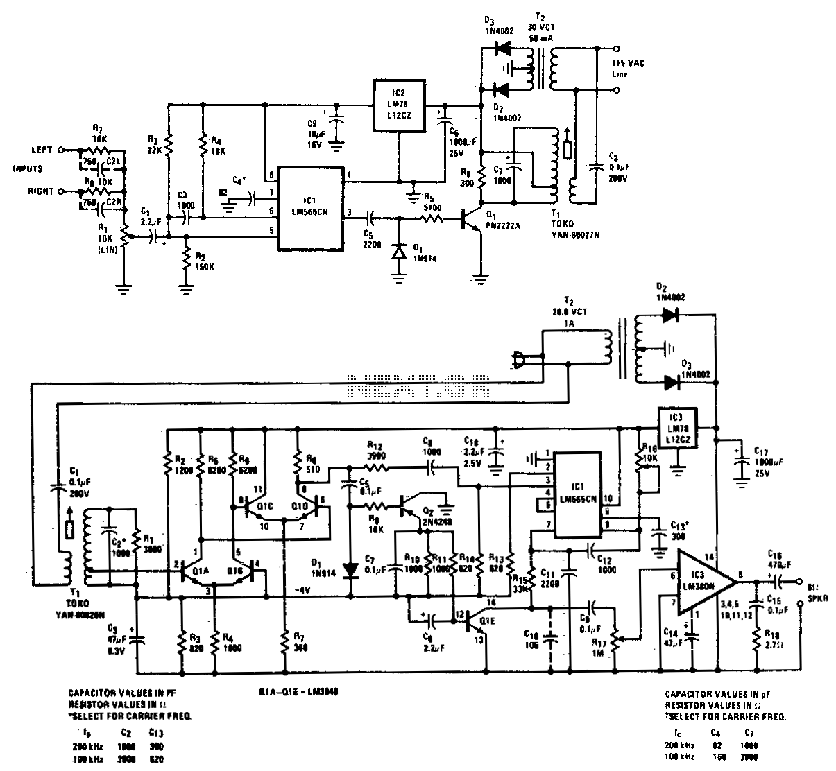
A high-quality, noise-free wireless FM transmitter and receiver operates over standard power lines. The complete system is designed for high-quality transmission of speech or music and can function from any AC outlet within a one-acre residential area. The frequency...
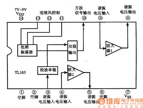
The following circuit illustrates the TL163 integrated circuit used in an ultrasonic remote control circuit diagram. Features include a detector, high-gain amplifier, and low-frequency capabilities. The TL163 integrated circuit serves as a pivotal component in ultrasonic remote control applications, facilitating...

This circuit diagram represents a remote control system utilizing DTMF (Dual Tone Multi-Frequency) signals. DTMF signals, generated by pressing numbers on a telephone keypad, serve as the control mechanism for the system. The DTMF tones are employed to modulate...
Here is a circuit of a remote control unit which makes use of the radio frequency signals to control various electrical appliances. This remote control unit has 4 channels which can be easily extended to 12. This circuit differs...