
Infrared Remote Control Jammer

The 555 timer is a versatile integrated circuit that can be configured in various modes, including astable, monostable, and bistable, making it suitable for a wide range of applications. In the context of a remote control jammer, the timer can be set up in an astable mode to generate a continuous square wave output. This output can then be used to interfere with the infrared (IR) signals typically emitted by remote controls.
The circuit generally consists of a 555 timer IC, resistors, capacitors, and an infrared LED. The resistors and capacitors determine the frequency of the output signal, which should be set to a value that effectively disrupts the frequency range of the remote control signals. The infrared LED emits modulated light at this frequency, which can overpower the signals sent by legitimate remote controls, thereby preventing them from functioning correctly.
Power supply considerations are also critical in this design. The circuit can be powered by a standard battery or a regulated power supply, ensuring that it operates consistently without interruptions. It is important to include a current-limiting resistor in series with the infrared LED to prevent damage due to excessive current.
In summary, the 555 timer circuit designed as a remote control jammer effectively generates a jamming signal that disrupts the operation of remote controls, making it a practical solution in scenarios where control over remote devices is necessary, such as in households with children. Proper component selection and circuit configuration are essential for achieving the desired performance and ensuring the reliability of the device.This 555 timer circuit Remote control Jammer device it s useful when we need to block someone to use the remote control (children that change frequently t.. 🔗 External reference
Related Circuits
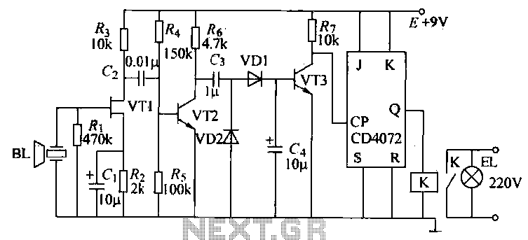
The T-40-16 and 555 ultrasonic transmitter circuit configuration consists of an ultrasonic transmitter T-40-16 and a 555 timer circuit. By adjusting the potentiometer RP, the oscillation frequency of the circuit can be changed. The output pulse frequency from the...
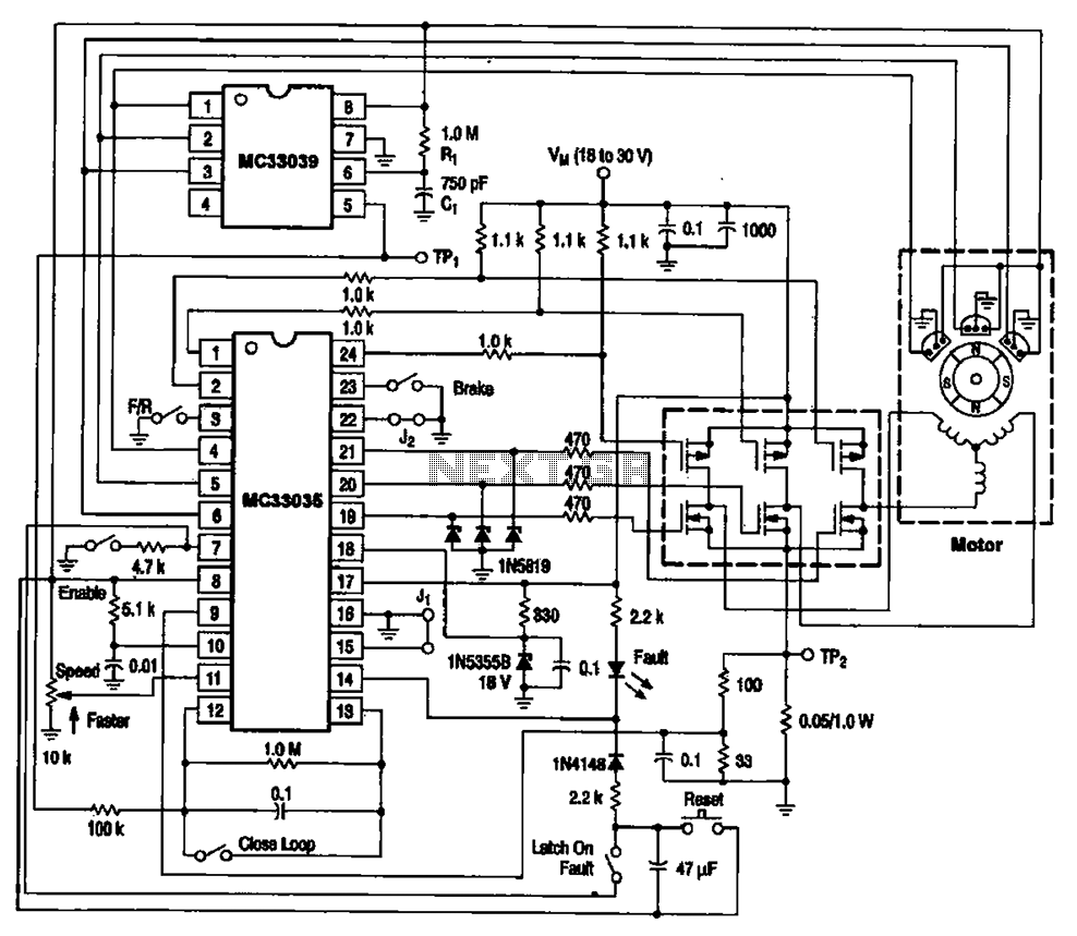
The brushless DC motor control circuit utilizing the MC33035 and MC33039 chips employs a combination of control circuits as illustrated in the figure. The primary components include the MC33035 motor control chip, the MC33039 brushless motor adapter, field effect...
This is a 0 - 6 MHz DDS VFO controlled by a PIC16F84 (or C84). The VFO is separated into two modules, the DDS module and the controller module. The PCB layout (double sided) for the DDS module is...
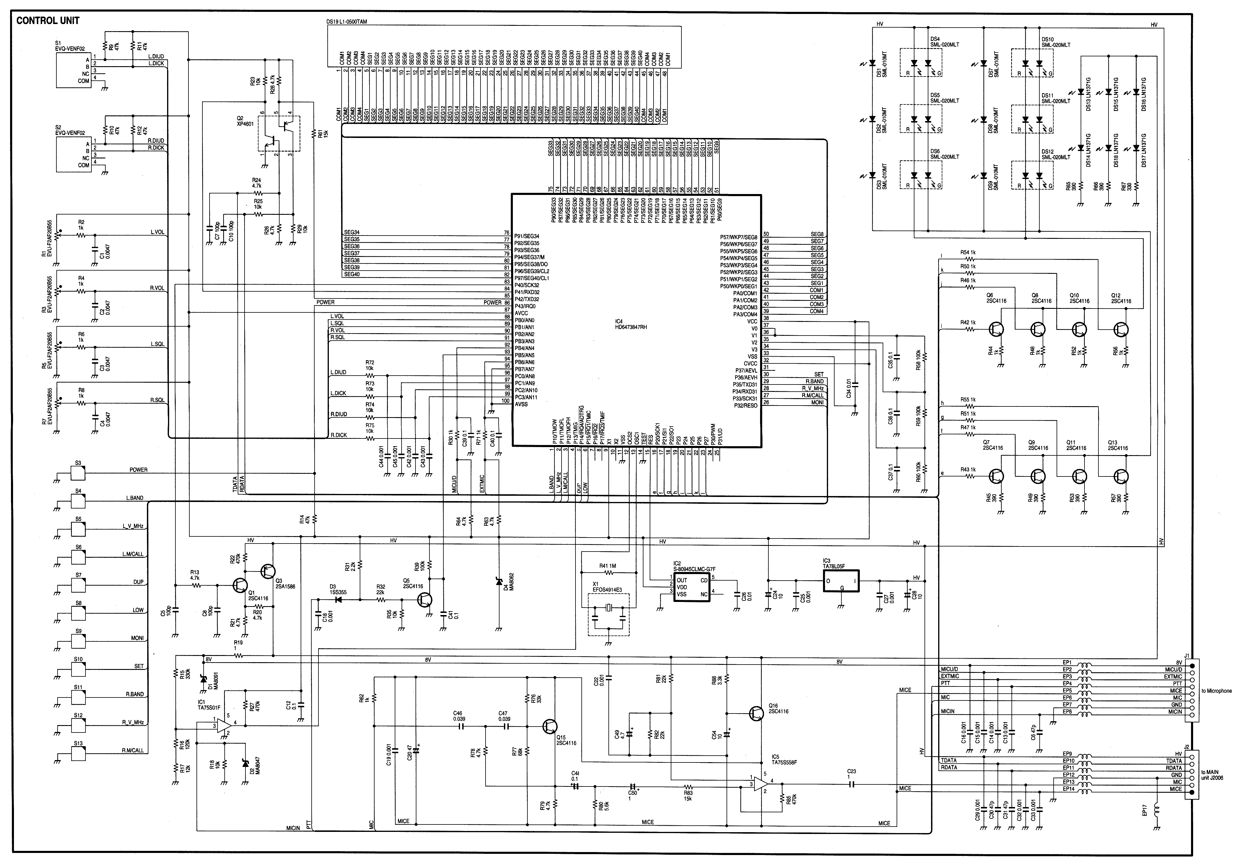
Radio Control Circuits PDF Manual Download. This document serves as a comprehensive guide to radio control circuits, intended for individuals seeking to understand the principles and applications of radio frequency (RF) technology in controlling various devices. The manual covers fundamental...
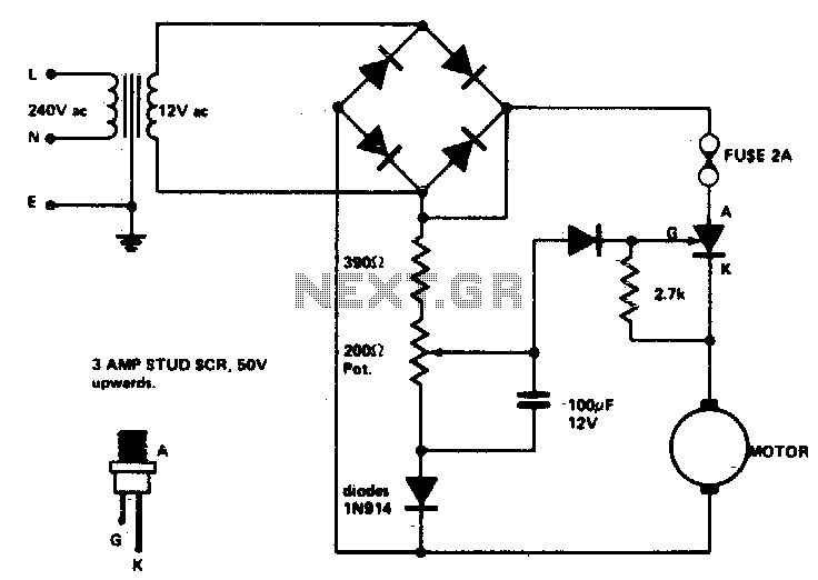
Low voltage speed control provides excellent starting torque and effective speed regulation. Additionally, a reversing switch can be integrated into the motor leads. Low voltage speed control circuits are essential in applications where precise motor control is required, such as...
This circuit is an Infra-Red Remote Control Tester designed to verify the functionality of any remote control that transmits infrared (IR) light. It operates on a 3V battery and offers several advantages, such as its compact size and the...