
Infrared Remote Control Tester

This circuit operates on the principle of light modulation, where the infrared (IR) signal from a remote control is detected by the phototransistor. The circuit consists of a power source, typically a battery, which provides the necessary voltage for operation. The phototransistor is sensitive to infrared light, allowing it to detect signals emitted by IR remote controls.
When the remote control is activated, it emits an IR signal that is received by the phototransistor. This signal causes the phototransistor to conduct, allowing current to flow through the circuit. The flow of current is then used to illuminate a visible-light LED. The LED serves as an indicator, visually confirming that the phototransistor is receiving IR energy and that the remote control is functioning correctly.
The circuit's simplicity makes it an effective tool for testing the functionality of IR remote controls. It can be easily assembled on a breadboard or a printed circuit board (PCB) using basic electronic components. The design can also be enhanced by incorporating additional features, such as adjustable sensitivity or a more sophisticated LED indicator system, to provide more detailed feedback on the strength of the received signal. Overall, this circuit is a practical application in the field of electronics, particularly for troubleshooting and testing IR remote devices. Using a battery, a phototransistor and a visible-light LED, this simple circuit is a " "go/no go"" tester fo r IR remote control devices. The illumination of the LED indicates that Ql is being modulated by IR energy.
Related Circuits
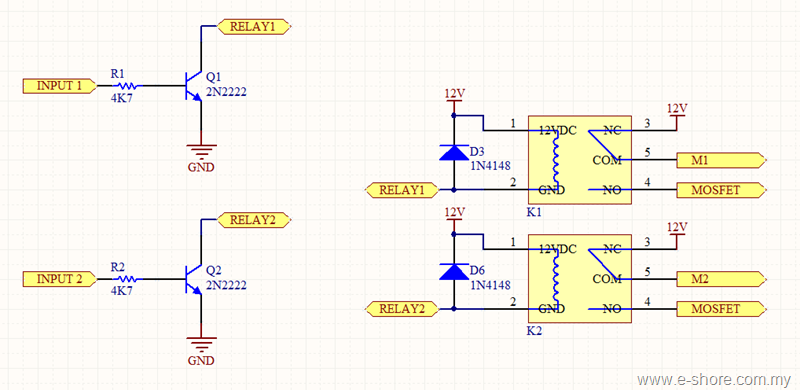
The circuit utilizes two sets of relays for each motor to switch the motor's direction, and one set of MOSFETs for each motor to control the motor's speed. The MOSFET and relay circuit will be divided into three parts...
High-end audio equipment is typically controlled digitally by a microprocessor (microcontroller) system. It is necessary to have a digital interface that allows for effective communication and control. High-end audio systems utilize a microcontroller to manage various functionalities, enabling precise control...
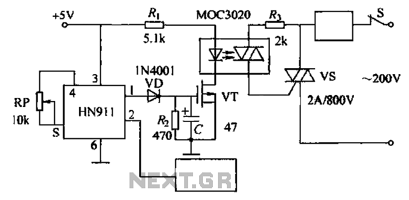
Automatic door control circuit diagram. It utilizes a pyroelectric infrared detection module, HN911, for human motion detection. A variable resistor (potentiometer) is used to adjust the delay time controlled by a transistor (VT). An optocoupler (MX: 3020) provides AC...

The ADC0804 converts the output voltages from the LM34/LM35 temperature sensors into digital signals that correspond to the measured temperature. These digital signals are then processed by the 8051 microcontroller. The temperature range for the LM35 sensor is from...
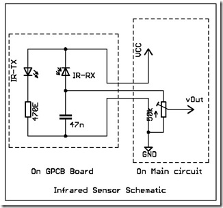
The following circuit illustrates a simple infrared sensor module circuit diagram. Features include a simple infrared sensor module and flame detection. The simple infrared sensor module circuit operates by utilizing an infrared (IR) transmitter and receiver pair. The IR transmitter...

A simple infrared-controlled switch can be operated using a TV remote control. The load can be any AC-powered device connected to the relay. The load activates for three minutes before turning off and can be used to switch on...