
Infrared Remote Receiver Has Four Outputs

The circuit operates by receiving infrared signals from a remote control, which are detected by the IR receiver (IRD1). The IR receiver outputs a low-level signal that is capacitively coupled to the base of the NPN transistor (Q1). The 220nF capacitor serves to filter out any DC bias, allowing only the AC component of the signal to pass through, effectively amplifying the signal strength. The common-emitter configuration of Q1 ensures that the amplified output can drive the subsequent circuitry without significant loss of signal integrity.
The 4047 monostable multivibrator (IC1) is configured to produce a pulse each time it receives a trigger from Q1. This pulse is then used to clock the 4017 decade counter (IC2), which counts the pulses and activates its outputs sequentially. The 4017 is designed to provide ten outputs, but in this application, it is limited to four outputs (O0-O3) for practical purposes. The reset mechanism is implemented by connecting the unused output (O4) to the reset pin (MR), ensuring that after the fourth button press, the counter resets and starts the counting sequence anew.
Powering the circuit is achieved through a transformer that steps down the mains voltage to a safer level, which is then rectified by a bridge rectifier to provide a stable DC voltage between 15 and 27V. This voltage is further regulated down to +12V and +5V using linear voltage regulators (REG1 and REG2), ensuring that the circuit components receive the appropriate voltage levels for optimal operation. The careful selection of resistors and capacitors in the circuit design guarantees reliable performance and efficient operation across a range of infrared remote control devices.This circuit enables any infrared (IR) remote control to control the outputs of a 4017 decade counter. It`s quite simple really and uses a 3-terminal IR receiver (IRD1) to pick up infrared signals from the transmitter.
IRD1`s output is then coupled to NPN transistor Q1 via a 220nF capacitor. Transistor Q1 functions as a common-emitter amplifier wi th a gain of about 20, as set by the ratio of its 10kO collector resistor to its 470O emitter resistor. Q1 in turn triggers IC1, a 4047 monostable which in turn clocks a 4017 decade counter (IC2). Basically, IC1 provides a clock pulse to IC2 each time a remote control button is pressed. If you don`t wish to use all 10 outputs from IC2, simply connect the first unused output to pin 15 (MR).
In this case, only the first four outputs (O0-O3) of the counter are used and so the O4 output is connected to pin 15 to reset the counter on the fifth button press. Power for the circuit is derived from the mains via a transformer and bridge rectifier which produces about 15-27V DC.
This is then fed to 3-terminal regulators REG1 & REG2 to derive +12V and +5V supply rails. 🔗 External reference
Related Circuits
Pressing the pushbutton on the transmitter activates a sound and/or light alert in the receiver. This system operates without wiring or radio frequencies; instead, the transmitted signal is conveyed through the mains supply line. It is suitable for use...
Utilizes a barium titanate transducer as a microphone, tuned with a 20 mH coil to generate peaks at control frequencies of 38.5 kHz and 41.5 kHz. A balanced discriminator detects the two ultrasonic tones. A frequency shift in the...
The TDA7000 is a well-known FM radio receiver integrated circuit (IC), also referred to as a one-chip FM radio receiver. It operates within the VHF FM band, covering frequencies from 70 to 120 MHz. Introduced in the 1980s, the...
TA1317ANG is a deflection processor integrated circuit (IC) designed for large and wide picture tubes. It includes an electronic width (EW) correction circuit, a vertical distortion correction circuit, and a dynamic focus correction circuit. The device can control various...
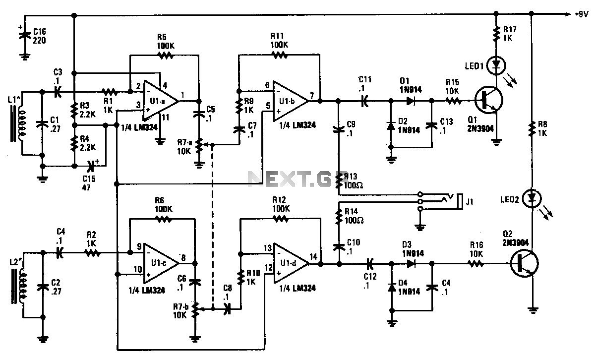
The tracer receiver is a stereo audio amplifier and detector circuit that operates at a frequency close to 1 kHz. Inductors L1 and L2 are hand-wound coils, each consisting of 200 turns of #26 wire on 2-inch ferrite cores,...
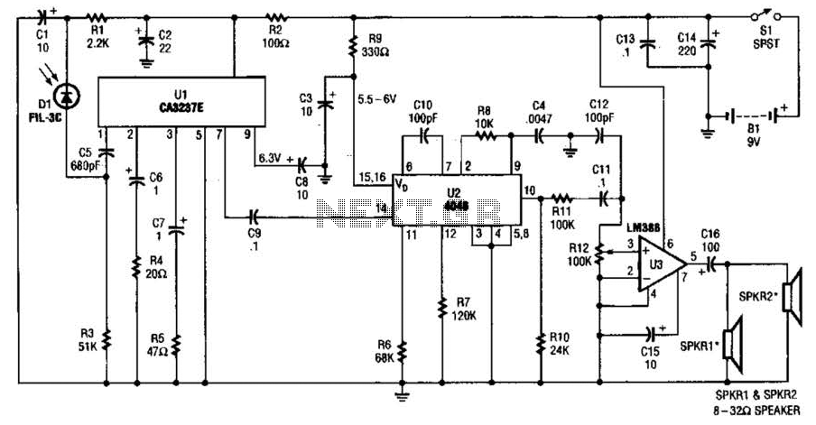
The infrared (IR) detector diode D1 captures the IR signal at approximately 40 kHz and transmits it to U1, a high-gain preamplifier, which then sends the signal to U2, a 4046 phase-locked loop (PLL) configured as a frequency modulation...