
Infrared transmitter

GP1U52X is quite hard component to get outside USA. European experiments can try to replace it with SFH 506 or SFH 507 from Siemens. Component list for IR transmitter: C1 1 nF, C2 10 nF, C3 220 nF, D1,D2 1N4148, D3 TIL31B (or other suitable IR LED), R1 1 kohm, R2 22 kohm trimmer, R3 120 ohm, U1 NE555, LM555 or similar.
The circuit designed for the IR transmitter utilizes a NE555 timer or similar IC (U1) configured in astable mode to generate a modulated 40 kHz signal. The frequency of the carrier wave can be adjusted by varying the resistance of R2, which is a 22 kohm trimmer. The output of the timer is connected to the anode of D3 (TIL31B or another suitable IR LED), which emits infrared light when the timer output is high. The use of 1N4148 diodes (D1 and D2) ensures that there is proper current flow and protection in the circuit.
Capacitors C1, C2, and C3 are used for filtering and stability in the circuit, with C1 providing decoupling for the power supply, C2 smoothing the output signal, and C3 coupling the output of the IR LED. Resistor R1 serves to limit the current flowing through the IR LED, ensuring it operates within safe limits, while R3 is used to pull the control signal to ground when the transmitter is off.
The control mechanism is straightforward; the LEFT/RIGHT CONTROL pin dictates the operational state of the transmitter. A logic high (+4 to +15V) activates the transmitter, while a logic low (+1V to -15V) deactivates it. This allows for easy integration with TTL or RS-232C level signals, facilitating various applications such as remote control systems or data transmission setups.
For receiving signals, the GP1U52X module is employed, which is sensitive to the 40 kHz carrier frequency. However, due to availability issues, alternatives like SFH 506 or SFH 507 can be explored, though they may not provide identical performance. The receiver's output can be connected to an RS-232 buffer circuit, allowing for compatibility with standard data communication protocols.
The overall design aims to create a functional and versatile IR transmission system, capable of supporting various applications, including the potential for wireless 3D glasses. However, practical implementation may require further refinement to achieve desired performance levels.This is an IR transmitting circuit which can be used in many projects (I designed this to try to make my 3D glasses wireless). This IR transmitter sends 40 kHz (frequency can be adjusted using R2) carrier under computer control (computer can turn the IR transmission on and off).
IR carriers at around 40 kHz carrier frequency are widely used in TV remote controlling and ICs for receiving these signals are quite easily available. The circuit can be controlled using any TTL or RS-232C level control signal which makes the interfacing very simple.
The circuit can be used for example for using computer to generate IR remote control signals or experimental IR data transmission. The circuit works so that when the input (LEFT/RIGHT CONTROL) pin is in logic high state (+4..15V) the transmitter is on and when it is in logic low state (+1V..-15V) the transmitter is off. The circuit can be also used for slow serial data transfer by connecting RS-232 data output to the transmitter module left/right control pin and connect the output of GP1U52X receiver module to RS-232 data input through suitable RS-232 buffer circuit.
Maximum data rates achievable are at around 1200-2400 bps speed. GP1U52X is quite hard component to get outside USA (in USA Radio Shack sells it cat. No. 276-0137). European experiments can try to replace it with SFH 506 or SFH 507 from Siemens. According some comments I have got none of the components I mentioned (GP1U52H, SFH506, SFH507) are no longer available, so you might not be able to get those. I don't know what would be a good more modern component replacement, because I have not tried other types than those myself.
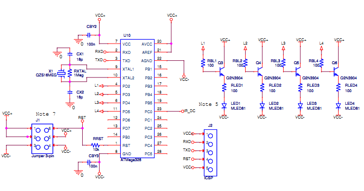
Component list for IR transmitter C1 1 nF C2 10 nF C3 220 nF D1,D2 1N4148 D3 TIL31B (or other suitable IR LED) R1 1 kohm R2 22 kohm trimmer R3 120 ohm U1 NE555, LM555 or similar IR receiver and sega glass interface circuit I designed the circuit to make my Sega 3D glasses wireless, but system did not work as well as I wanted it to work. I used the circuit below to receiving the IR signals and controlling the IR glasses. 🔗 External reference
Related Circuits

This circuit functions as a voice transmitter utilizing a pair of BC548 transistors. While these transistors are not specifically designed for RF applications, they still yield satisfactory performance. An ECM microphone insert from Maplin Electronics, order code FS43W, is...
Small Radio Transmitter. This article contains information about building a small radio transmitter, which has a PCB measuring 1.75 x 2.5 inches (45 mm x 68 mm) and offers a range of approximately 30 yards. The small radio transmitter is...
In a class project, each student was required to select one of three technology platforms to design, simulate, prototype, and build, including PCB layout and ordering, all within a ten-week timeframe. The available platforms were: H-bridge Motor Controller, Infrared...
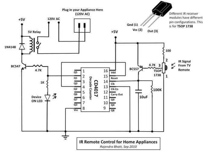
The infra-red (IR) toggle switch project described here is aimed to provide control mechanism for electrical appliances that do not have remote operation features. The goal is to construct a black box where you can plug-in your 120V AC...
The Muntz one-tube design can be significantly enhanced by incorporating an audio preamplifier stage. This modification increases sensitivity, allowing for full modulation with lower-level signal sources, such as certain older CD players and ceramic phono cartridges. Additionally, implementing negative...
This transmitter was designed from the ground up to provide very high sound quality, coupled with excellent frequency stability, reliability, etc. It can be used as a standalone transmitter to serve a medium-sized town, or as an exciter to...