
80 Watt stereo transmitter

The textbook way of processing and encoding a stereo signal for FM transmission goes like this: 1) Take both channels and low-pass-filter them at 15kHz, with steep rolloff; 2) Apply pre-emphasis. Depending on the part of the world, it should have either a 75µs or a 50µs time constant; 3) Strictly limit the audio level to ensure that overdeviation cannot happen; 4) Create a stable, clean 38kHz sine wave; 5) Subtract the right channel from the left channel, and multiply the result with the 38kHz carrier; 6) Create a clean 19kHz sine wave, phase-locked to the 38kHz one; 7) Add the left channel, right channel, the (L-R)*38kHz signal, and the 19kHz signal, with specific amplitudes.
There are several ways to implement this algorithm. Modern factory made transmitters often do the whole thing digitally, in a DSP. But it's still less expensive and simpler to do in the analog domain. That can be done in various ways too, and far too many transmitters these days use ultra cheap, mediocre methods like hard-switched multipliers based on CMOS switches. They do work, but are very noisy! My design instead uses a true, high quality analog multiplier for that task. As a result, the signal from my transmitter is as good as the very best signals I can receive locally, and MUCH better than the bulk of them!
Here is the schematic diagram. You probably won't be able to read it at this resolution, so better click on it, save it in full resolution, print it, and refer to it for the following explanation. If you have trouble opening the large version, right-click on the diagram, so you can save it to disk, then open it using IrfanView or any other GOOD image viewer. This is valid for all drawings on this page. The full resolution drawings are large, and depending on the amount of memory in your computer, some web browsers cannot open them and will report a broken link.
The two single-ended line-level audio signals enter through feedthrough capacitors, and are welcomed by an LC low-pass filter to get rid of any RF that could be on them. In each channel there is a buffer stage, and then a combined pre-emphasis and soft limiter stage. The advantage of doing the limiting and the pre-emphasis in one step is that it avoids overdeviating from loud treble sounds, or having loud bass sounds flatten out the treble, without the need of a multiband limiter. The gain of the non-limited portion of the audio signals is adjustable by means of trimpots. Then comes a six-pole low pass filter that removes signals above 15kHz.
A 74HC4060 chip derives the 38kHz and 19kHz signals, as square waves, from a custom-made quartz crystal. Two resonant circuits using ferrite pot cores turn these square waves into very clean, low noise sine waves. Trimpots allow to set the levels, while the adjustable cores of the inductors allow precise tuning. Jumpers allow to disable each of these signals for testing and adjustment purposes.This transmitter was designed from the ground up to provide very high sound quality, coupled with excellent frequency stability, reliability, etc. It can be used as a standalone transmitter to serve a medium-sized town, or as an exciter to drive a kilowatt-class power amplifier to serve a large city.
It is designed to work from 13.8V nominal voltage, so that it can be run from a common communications power supply in parallel with a backup battery. In the event of a power cut, the transmitter can keep operating from the battery, at slightly reduced power as the voltage drops.
It consists of four modules, the three most important of which are ready, tested, and described below. The fourth module has not yet been built, and might never be built, but I will describe its basic functions so that you can design it, if you want.
The RC4200 analog multiplier used in this stereo encoder seems to have gone out of production. Before considering the construction of this circuit, make sure you can actually find this IC, or else be sure you know how to modify the circuit to use a different analog multiplier, such as the AD633 or other one you might find. The textbook way of processing and encoding a stereo signal for FM transmission goes like this: 1) Take both channels and low-pass-filter them at 15kHz, with steep rolloff; 2) Apply pre-emphasis.
Depending on the part of the world, it should have either a 75µs or a 50µs time constant; 3) Strictly limit the audio level to ensure that overdeviation cannot happen; 4) Create a stable, clean 38kHz sine wave; 5) Subtract the right channel from the left channel, and multiply the result with the 38kHz carrier; 6) Create a clean 19kHz sine wave, phase-locked to the 38kHz one; 7) Add the left channel, right channel, the (L-R)*38kHz signal, and the 19kHz signal, with specific amplitudes. There are several ways to implement this algorithm. Modern factory made transmitters often do the whole thing digitally, in a DSP. But it's still less expensive and simpler to do in the analog domain. That can be done in various ways too, and far too many transmitters these days use ultra cheap, mediocre methods like hard-switched multipliers based on CMOS switches.
They do work, but are very noisy! My design instead uses a true, high quality analog multiplier for that task. As a result, the signal from my transmitter is as good as the very best signals I can receive locally, and MUCH better than the bulk of them! Here is the schematic diagram. You probably won't be able to read it at this resolution, so better click on it, save it in full resolution, print it, and refer to it for the following explanation.
If you have trouble opening the large version, right-click on the diagram, so you can save it to disk, then open it using IrfanView or any other GOOD image viewer. This is valid for all drawings on this page. The full resolution drawings are large, and depending on the amount of memory in your computer, some web browsers cannot open them and will report a broken link.
The two single-ended line-level audio signals enter through feedthrough capacitors, and are welcomed by an LC low-pass filter to get rid of any RF that could be on them. In each channel there is a buffer stage, and then a combined pre-emphasis and soft limiter stage. The advantage of doing the limiting and the pre-emphasis in one step is that it avoids overdeviating from loud treble sounds, or having loud bass sounds flatten out the treble, without the need of a multiband limiter.
The gain of the non-limited portion of the audio signals is adjustable by means of trimpots. Then comes a six-pole low pass filter that removes signals above 15kHz. A 74HC4060 chip derives the 38kHz and 19kHz signals, as square waves, from a custom-made quartz crystal. Two resonant circuits using ferrite pot cores turn these square waves into very clean, low noise sine waves.
Trimpots allow to set the levels, while the adjustable cores of the inductors allow precise tuning. Jumpers allow to disable each of these signals for testing and adjustment purposes. 🔗 External reference
Related Circuits
Wireless FM Transmitter. The image displays a wireless FM transmitter alongside a pocket radio and a yellow disk for size comparison. When the user speaks into the transmitter, others can hear the transmission on any FM radio. The wireless FM...
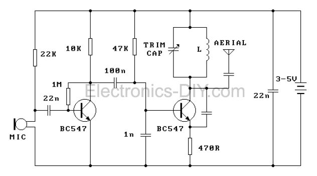
This FM transmitter is one of the simplest and most basic designs that can be built while still providing a useful transmitting range. Despite its small component count and 3V operating voltage, it is surprisingly powerful, capable of transmitting...
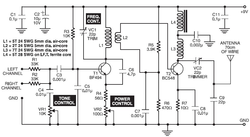
A high-quality FM transmitter circuit designed for use with amplifiers, providing a strong signal strength with a range of up to 500 meters and a power output of approximately 200 mW. This FM transmitter circuit is engineered to deliver reliable...
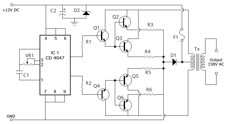
This is the simplest circuit for a 100-watt inverter that generates 220V AC from 12V DC. It is considered simple because it utilizes a minimal number of components in its design, making it challenging to create a circuit with...
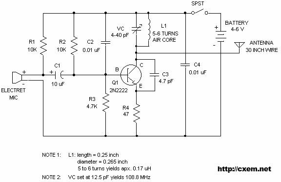
The following plans outline the construction of a compact tracking transmitter that can be detected using an FM broadcast band radio receiver. The transmitter operates on a battery voltage range of 3 volts to 9 volts and has a...
Sensitive FM Transmitter. Additional Notes: The default for the capacitors type is ceramic, preferably the NPO 1% type or equivalent. However, nothing critical is here; any type can be used. The sensitive FM transmitter circuit is designed to operate in...