
Infrared transmitter circuit schematic

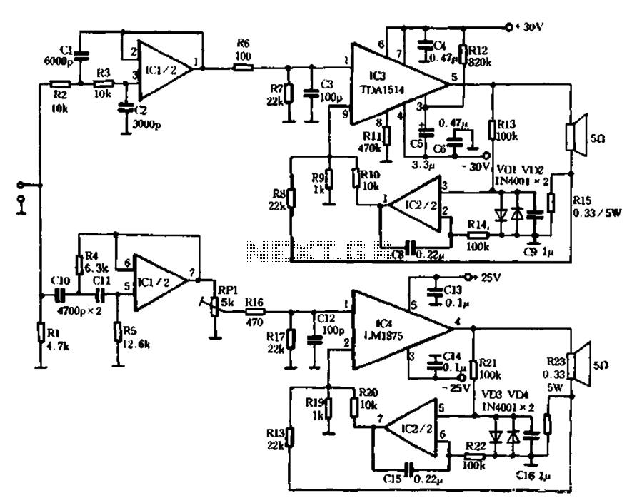
The infrared transmitter circuit operates on the principle of pulse width modulation (PWM) to encode audio signals for wireless transmission. The LM567 tone decoder serves as a critical component, enabling the detection of specific frequencies, which enhances the system's ability to filter out noise and improve signal integrity. The audio input, which must meet a minimum amplitude of 50 mV peak-to-peak, is first amplified by the transistor T1. This amplification stage is essential to ensure that the audio signal is sufficiently strong for effective modulation.
The modulation is performed by IC1, which is responsible for converting the amplified audio signal into a modulated infrared signal. The frequency of this modulation can be fine-tuned using the adjustable potentiometer P2, allowing for flexibility in the operating frequency of the transmitter. This adjustment capability is crucial for optimizing performance in various environments and applications.
The circuit also includes additional components such as the EPM7128STC100-15, which is a field-programmable gate array (FPGA) that can be used for further processing or control functions within the system. The DG413DY is a dual analog switch that may be utilized for routing signals within the circuit, while the AD620AR is an instrumentation amplifier that can enhance the signal conditioning stage, ensuring that the audio signal is clean and accurately represented before modulation.
Overall, this infrared transmitter circuit is designed for efficient audio signal transmission using infrared light, making it suitable for various applications, including remote controls, wireless audio systems, and other communication devices that require reliable and effective signal transmission.This infrared transmitter use PWM, pulse width modulation The transmitter is equiped with LM 567, tone decoder circuit. Audio signal ( at least 50mVvv ) is amplified with T1 and then it is used to modulate IC1. Infrared transmitter frequency is adjusted with P2 between 25 and 40KHz. IR transmitter circuit diagram EPM7128STC100-15 DG413DY AD620AR. 🔗 External reference
Related Circuits

Digital Command Control (DCC) provides significant advantages over traditional DC analog control systems, primarily due to its simplified wiring. DCC enables the individual control of multiple locomotives on the layout without requiring electrical isolation of track sections. The main...

This circuit is designed to provide automatic current limiting up to 8.4 A. Unlike traditional current limiters that rely solely on a resistor, this circuit minimizes voltage drop until a specified current threshold is exceeded. The current limit can...
The mechanical and electrical schematic in Figure 5 illustrates a simple circuit comprising several components. The first component is an electronic crossover section utilizing the NE5532 operational amplifier, which is known as the "Emperor of the op-amp." This section...
Bridged resistive sensing elements are commonly used in resistive type sensors and transducers. This type of sensor requires a biasing voltage to operate. The LM10 provides low... Bridged resistive sensing elements are integral components in various resistive sensors and transducers,...
This relay circuit is controlled by nearly any type of infrared remote controller. It operates under the assumption that most remote controllers utilize high-frequency modulated infrared light. By filtering out unmodulated or low-frequency modulated signals, this circuit effectively eliminates...
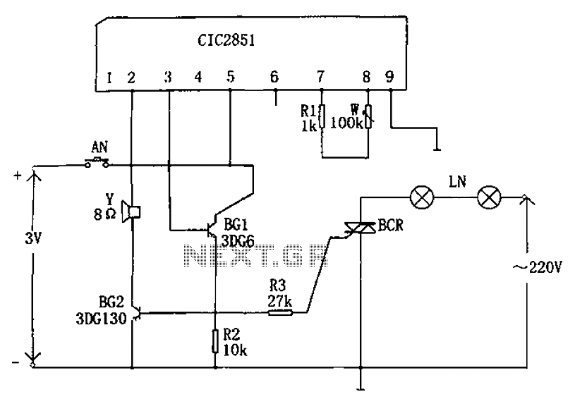
The non-contact lantern control circuit includes an integrated music IC (CIC2851), transistors (BG1 and BG2), a thyristor (SCR), and other components. When the switch is pressed (AN), the CIC2851 is activated, causing the output terminal (pin 3) to emit...