
Free energy collector circuit

It appears that antenna placement is critical to output. By constructing multiple circuits and connecting their outputs together, it is possible to generate sufficient energy to power a house. Each unit requires its own antenna. Experimentation with different lengths and sizes of antennas is advised, as RF power levels vary across different locations on Earth. Proximity to large cities or transmitters, where RF levels are significantly higher, greatly enhances circuit performance. To optimize antenna design, consider this unit as an all-frequency radio receiver. A critical consideration is the earth ground of the circuit, which must be adequately conductive. An effective earth ground should consist of a metallic conductive pipe or rod. Utilizing the existing earth ground of a residence or purchasing a new earth ground and driving it as deep as possible into the ground will yield the best results.
This circuit design can be visualized as a simple RF energy harvesting system. The central component is the antenna, which captures ambient radio frequency signals. The antenna's length and orientation play a vital role in its efficiency; thus, a wire length of over 150 feet is recommended to maximize the surface area for RF capture. The circuit should ideally be positioned close to the antenna to minimize losses.
The output stage includes a rectifier circuit to convert the AC signal received from the antenna into a usable DC voltage. This DC output can be stored in a capacitor or used directly to power devices. The passive detection capability is an additional feature that can be integrated into the circuit, allowing it to respond to changes in the electromagnetic environment, such as the presence of large metallic objects or seismic activity.
In practical applications, multiple units can be deployed across a geographical area to create a network of RF harvesting systems. Each unit would require careful calibration and testing to determine the optimal antenna configuration for its specific location. The earth ground connection must be robust to ensure the circuit operates effectively, as poor grounding can lead to inefficiencies and reduced output.
Overall, this circuit presents a unique approach to harnessing ambient radio frequency energy, with potential applications in sustainable energy generation and environmental monitoring.This circuit converts surrounding radio frequency waves to electric power. It can provide 40 Volts at 10 Watts indefinitely. The output power can be improved playing with the antenna. Placing the antenna near large metal objects gives more power. Antenna should be more than 150 feet long wire, placed horizontally as high as you can for best results. The pointing direction also is critical to the output. Keep the circuit as close to antenna as posible. You can also experiment with dishes etc. The circuit also acts as a passive detector. When large metal objects passes the power gets higher. Also its sensitivity can detect energy changes on earth and so it can used as early warning of seismic activity
It appears that antenna placement is critical to output. By constructing many of these circuits and connecting their outputs together, you could produce the energy to power a house. Remember each unit needs its own anntena. The best thing to do is to experiment with diferent lengths and sizes of anntenas. Every place on earth has diferent levels of RF power. Ofcource near large citys or near transmiters where RF is huge on air, the circuit works much better.
To get an idea of making the best anntena, Imagine that this unit as an all frequency radio reciever. A very critical point to consider is the earth ground of the circuit which has to be properly conductive.
An earth ground should consist of some type of metallic, conductive pipe or rod. Use the earth of your house or buy a new earth ground from the market hammer it as deep as you can for best results.
Related Circuits
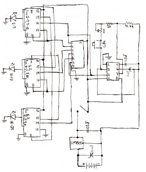
Here is the schematic for the circuit. Solder all the components onto a perfboard. The drawings may not be very clear. Essentially, the 555 timer generates a pulse. The circuit utilizes a 555 timer IC configured in astable mode, which...
This circuit is a simple analog multiplier. The operation of the circuit can be understood by considering A2 as a controlled gain amplifier that amplifies V2, with its gain dependent on the ratio of the resistance of PC2 to...
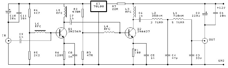
A high-efficiency, simple two-transistor VHF amplifier electronic circuit project can be developed using the provided circuit diagram. This VHF amplifier circuit achieves a significant efficiency with a gain of approximately 16 dB and does not require any tuning or...
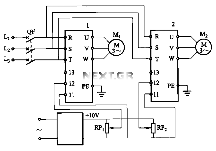
Adjust the potentiometers RPi and RPz to modify the speed of two motors. The circuit utilizes two potentiometers, designated as RPi and RPz, to control the speed of two separate motors. Each potentiometer is connected in a voltage divider configuration,...
This circuit activates an alarm when its sensor comes into contact with water. It employs a 555 astable multivibrator that generates a tone of approximately 1 kHz upon water detection. The circuit consists of a 555 timer configured in astable...

This article discusses the functionality of a super-regenerative FM receiver. The principle behind this receiver utilizes high-gain miniature integrated circuits, resulting in a simple and innovative circuit design. It achieves the performance level of standard FM receivers while addressing...