
Novel FM receiver circuit diagram

Super-regenerative receiver FM wave, in fact, will be converted into the FM wave amplitude modulation, while the wave amplitude modulation envelope detector to obtain a low-frequency signal. FIG transistor VTl and peripheral components typical super-regenerative FM receiver circuit, and the FM wave signals into AM signals and envelope detection output audio signal.
If you remove the end of the audio signal directly from R3 envelope detection after amplification, the resulting audio noise is relatively large, but the receiver selectivity deteriorated. Thus, this uses from VT1 emitter by induction to the series circuit of the high-frequency choke AM signal further frequency amplification, detection output audio signals to overcome these shortcomings.
When VT1 work on the high-frequency choke will form an AM modulated signal FM programs. This signal is coupled to a dedicated receiver AM amplitude modulated wave on micro IC1 7642 demodulated by the transformer T1. Piece integrated circuit comprises a high-impedance input stage, the whole process of the three high-frequency amplification and detection output, and gain greater than 70dB.
The audio signal output from the detector is coupled to the capacitor C9 low-frequency amplification transistor VT2, CZ through the headphone jack output to a load (headset) to listen to radio programs. High-frequency choke T2 is to prevent high-frequency signal to the battery and other parts to form a loop and are attenuated, but the audio signal but no impediment.
Capacitor C6 for small ceramic trimmer capacitors that require access to the movable piece in figure A welding end, the objective is to reduce the impact on the human body sensors Tuning tuning circuit. High-frequency inductors L1 using µ1.0mm µ5.0mm enameled wire wound on the rod 3 turns bodiless.
Selection of high-frequency choke transformer T1 removed from the old machine AM-IFT miniature in the week around the system, the original wound on "workers" shaped core wire removed, and then re-enameled high strength µO.07mm around the primary part of the high-frequency choke coil wound about 50, about 150 secondary inductive coil around the part added after adjusting magnetic cap and outer shield can be. Selection of high-frequency choke T2 holes ring, enameled wire with µ0.2mm each well made around 10 laps.
By adjusting the first R1 to VT1 collector current adjusted to 0.3mA-0.5mA, adjust the resistance R7 VT2 collector current of about 2mA. At this point you can use headphones to listen to "trace" the sound of flowing water (electrical noise), by adjusting the capacity of C6 to listen to FM radio programs.
Fine tune L1 and T1 turn away from magnetic cap to keep the volume of the best sound quality.
Related Circuits
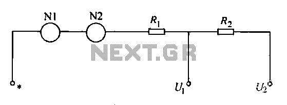
A voltmeter operates through a measuring mechanism in a specified circuit, utilizing a moving coil in series with additional resistance. The fixed coil is denoted as N1, while the moving coil is designated as N2. The additional resistances are...
The electronic fishing shrimp machine circuit consists of an astable oscillator, an inverter circuit, and a high-voltage output circuit, as depicted in Figure 20. The astable oscillator circuit includes a time-base integrated circuit (IC), resistors R3 and R4, a...

This circuit is an oscillator utilizing astable mode operation, based on the 555 timer integrated circuit (IC). It functions as a free-running oscillator. The operation begins when the capacitor (C) charges towards 2/3 of the supply voltage (V+) through...
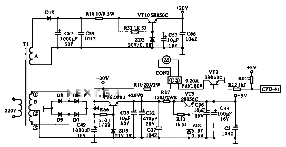
The JYC-22F type cooker low voltage power supply circuit is depicted. An AC 220 V power supply voltage is applied to a low-voltage transformer. The transformer has a primary winding (Tl) and two secondary windings (A and B), with...
This circuit design has not been tested by staff. The design, as submitted by the designer, is believed to be correct; however, there is no guarantee of its accuracy. The content provided may be inaccurate, inappropriate, or misguided. There...

The duration for which the circuit remains active is determined by the time required for the stored electrical current to leak back into the circuit, which keeps the transistor and the entire circuit energized. A resistor is present that...