


Simple Staircase Generator
#decade counter
#divider
#switch debouncer
#resistor
#self-generating
#pulse generation
#timing circuit
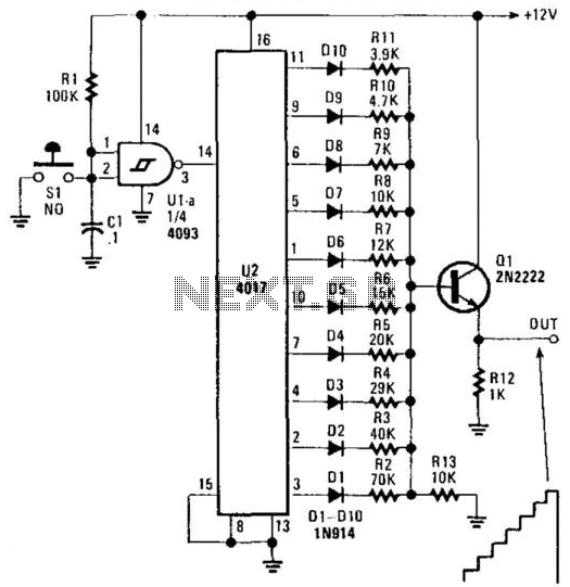
Description: U2 is a decade counter/divider, U1 is used as a switch debouncer. For a self-generating system, connect a resistor between pins 2 and 3 of U1, value that should be between 10 KOhm and several, depending on desired frequency. C1 can also be varied to change frequency. Also, S1 can be omitted in the self-generating version.
The circuit described involves two primary components: U1, which functions as a switch debouncer, and U2, a decade counter/divider. The switch debouncer (U1) is essential for eliminating noise from mechanical switches, ensuring that when a switch is pressed, only a single transition is registered, rather than multiple erroneous transitions that could occur due to contact bounce.
In the self-generating configuration of this circuit, a resistor is connected between pins 2 and 3 of U1. The value of this resistor should typically be in the range of 10 KOhm, but it can be adjusted to higher values depending on the desired frequency output of the system. This resistor, in conjunction with the capacitor C1, forms an RC timing circuit that determines the frequency of oscillation. By varying the capacitance of C1, the frequency can be fine-tuned to meet specific application requirements.
Additionally, S1, which may serve as an external switch input in non-self-generating configurations, can be omitted in the self-generating version. This allows the circuit to operate independently without external input, making it suitable for applications where a continuous output signal is required. The output from U2, as a decade counter, can provide a sequence of digital signals that can be used for various applications, such as driving LEDs, frequency division, or other digital logic circuits.
Overall, this circuit configuration is useful for creating reliable timing and counting applications in digital electronics, with flexibility in frequency adjustment through passive component selection. U2 is a decade counter /divider, Ul is used as a switch debouncer. For a self-generating system, connect a resisor
The circuit described involves two primary components: U1, which functions as a switch debouncer, and U2, a decade counter/divider. The switch debouncer (U1) is essential for eliminating noise from mechanical switches, ensuring that when a switch is pressed, only a single transition is registered, rather than multiple erroneous transitions that could occur due to contact bounce.
In the self-generating configuration of this circuit, a resistor is connected between pins 2 and 3 of U1. The value of this resistor should typically be in the range of 10 KOhm, but it can be adjusted to higher values depending on the desired frequency output of the system. This resistor, in conjunction with the capacitor C1, forms an RC timing circuit that determines the frequency of oscillation. By varying the capacitance of C1, the frequency can be fine-tuned to meet specific application requirements.
Additionally, S1, which may serve as an external switch input in non-self-generating configurations, can be omitted in the self-generating version. This allows the circuit to operate independently without external input, making it suitable for applications where a continuous output signal is required. The output from U2, as a decade counter, can provide a sequence of digital signals that can be used for various applications, such as driving LEDs, frequency division, or other digital logic circuits.
Overall, this circuit configuration is useful for creating reliable timing and counting applications in digital electronics, with flexibility in frequency adjustment through passive component selection. U2 is a decade counter /divider, Ul is used as a switch debouncer. For a self-generating system, connect a resisor
between pins 2 and 3 of a Ul value that should be between 10 KOhm and several , depending on desired frequency, Cl can also be varied to change frequency. Also, SI can be omitted in the self-generating version.
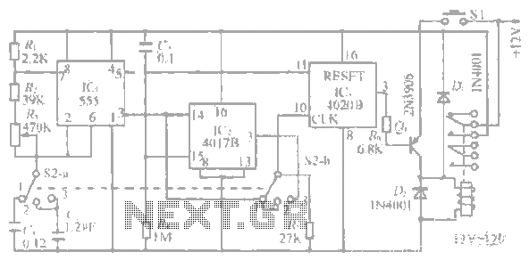
1-20 minutes a timing circuit
The system operates between 10 minutes to 2 hours, featuring a 100-line bell controlled by a multi-gear stick labeled S2 41f. The integrated circuit (IC) functions as a self-excited multivibrator. The device can manage binary pulses ranging from 3 to...
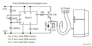
freeze protector circuit
This is a simple freeze protector circuit diagram, also known as a timing circuit. It serves as a hobby project for beginners. This circuit can automatically operate any device after a fixed time once AC power supply is restored. The...
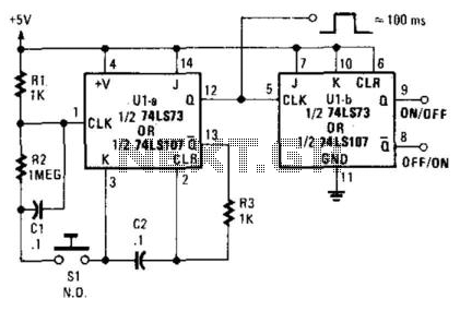
Switch Debouncer
A 7473 JK flip-flop U1A is configured as a monostable multivibrator to drive U1B, functioning as a switch debouncer. The circuit features a self-clearing mechanism during power-up, providing a 100-ms pulse at pin 12 of U1A.
The circuit utilizes the 7473...
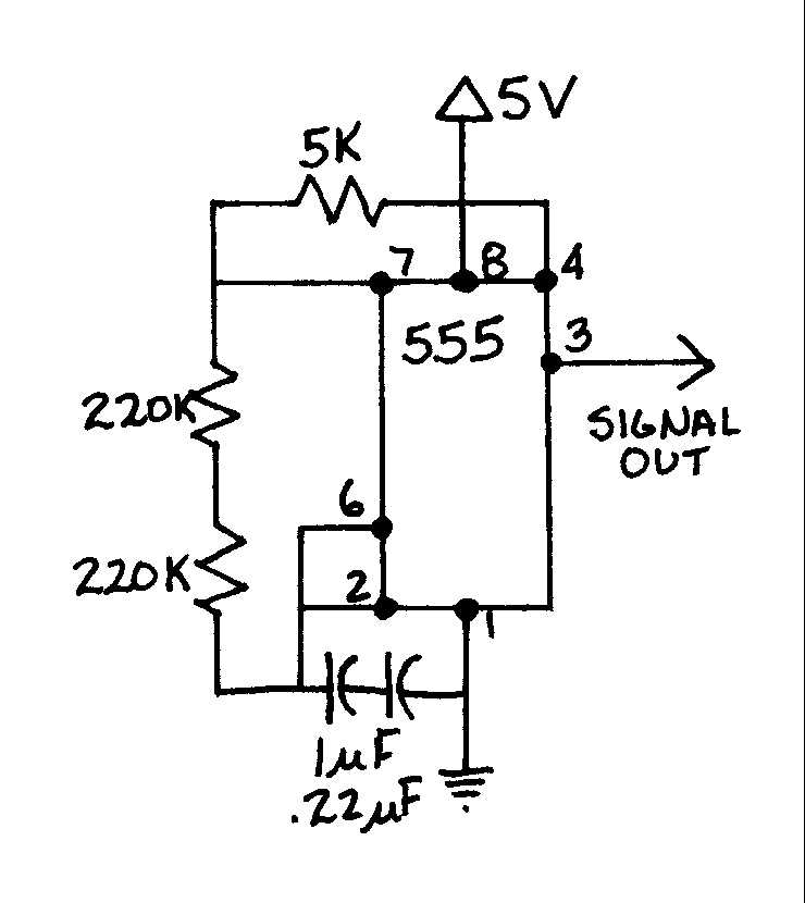
EGR 450 Manufacturing Controls Project
A timing and counting circuit utilizing integrated circuit chips with seven-segment LED displays is employed to show the current lap time, previous lap time, and total number of laps completed on a 1/64th-scale slot car racetrack. A switch activated by...
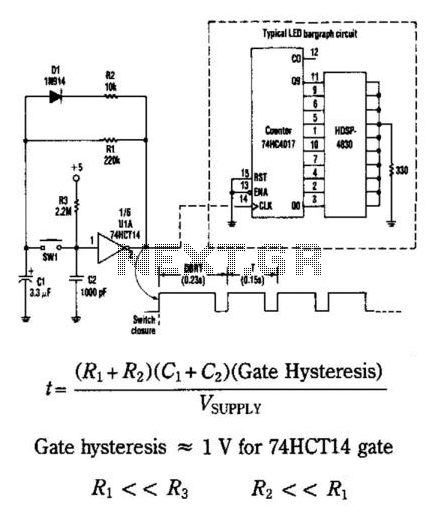
Switch Debouncer With Auto Repeat
This circuit generates an output pulse when the pushbutton SW1 is pressed. It also functions as a hysteresis gate oscillator. Diode D1 and resistor R2 introduce asymmetry into the circuit. The delay before repeat time (DBRT) is influenced by the...
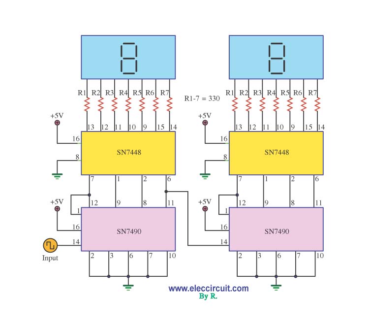
Digital Decade Counter Schematic
A decade counter circuit is an electronic circuit designed to perform a sequence of numerical calculations, allowing for either forward or backward counting. Forward counting refers to the circuit counting from smaller to larger numbers, while backward counting is the...
1-20 minutes a timing circuit
The system operates between 10 minutes to 2 hours, featuring a 100-line bell controlled by a multi-gear stick labeled S2 41f. The integrated circuit (IC) functions as a self-excited multivibrator. The device can manage binary pulses ranging from 3 to...
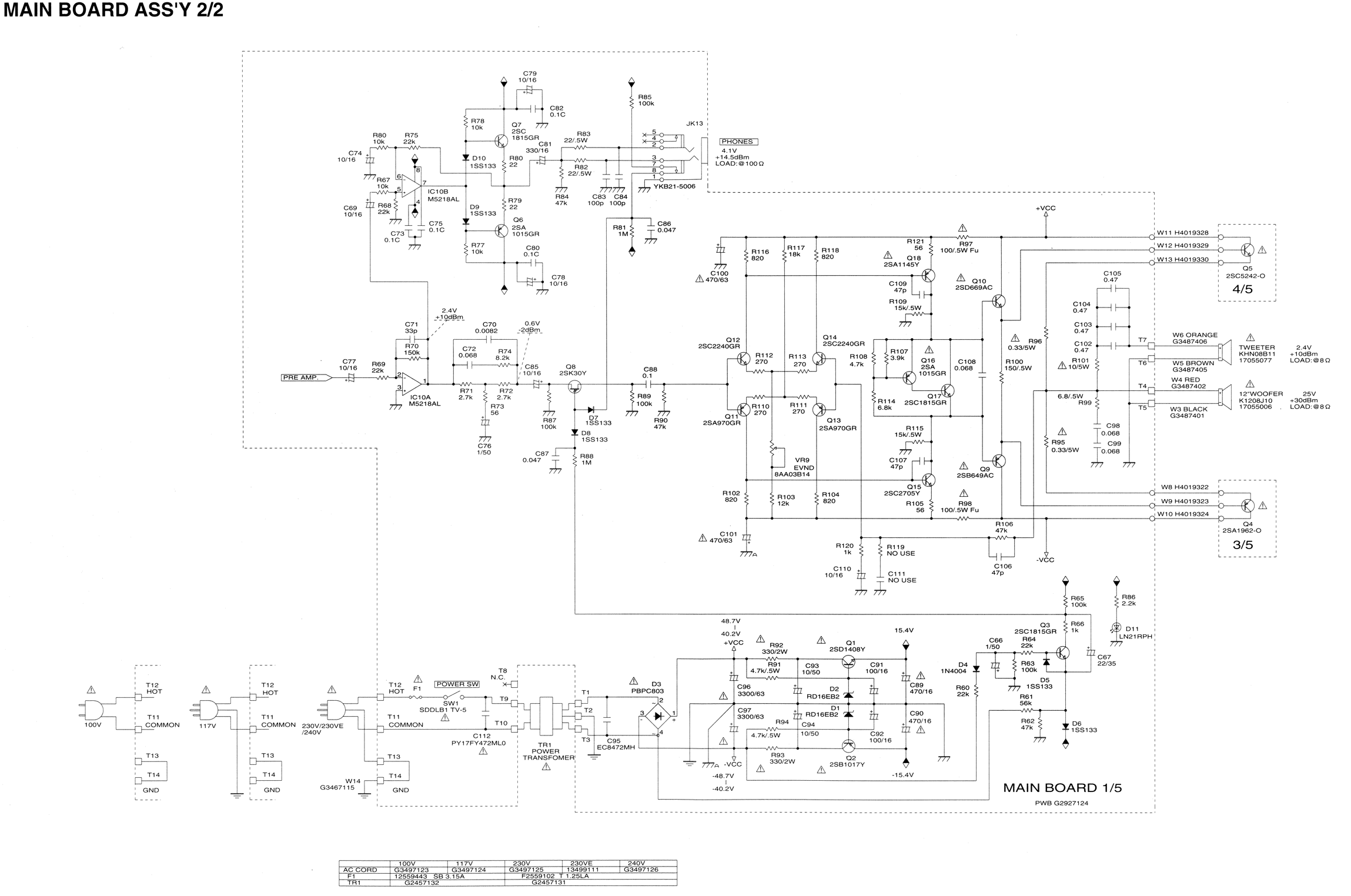
I burned out some resistors on the circuit board of my Roland
Some resistors on the circuit board of a Roland KC-300 amplifier have burned out and are so charred that their specifications cannot be determined. The resistors in question are R82, R83, R85, R92, and R93. Resistors R92 and R93 are...
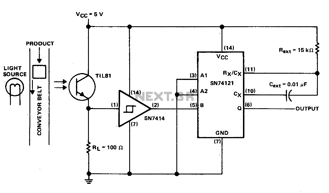
Pulse generation by interrupting a light beam
This circuit generates a pulse when an object on the conveyor belt obstructs the light source. The light source continuously keeps the phototransistor activated, resulting in a high logic level voltage at the Schmitt-trigger inverter and a TTL-compatible low logic...