
5A H-Bridge Module Pinout Circuit Schematic for Bipolar DC Motor

The 5A H-Bridge Module serves as a critical component in controlling the direction and speed of a Bipolar DC motor. It allows for bidirectional control of the motor by enabling the flow of current in either direction through the motor windings. The H-Bridge configuration typically consists of four switches (transistors or MOSFETs) arranged in an "H" pattern, which facilitates the reversal of current flow.
The J1 connector terminal set is used for power supply and motor connections, while the J2 header set provides an interface for control signals. The J2 pinout typically includes pins for PWM (Pulse Width Modulation) control, direction control, and ground connections. The PWM signal modulates the effective voltage supplied to the motor, allowing for speed control, while the direction control pin determines the rotation direction of the motor.
In practical applications, the H-Bridge Module can be interfaced with microcontrollers or other control circuits to achieve precise motor control. Proper heat dissipation measures, such as heat sinks or fans, may be necessary to prevent overheating during operation, especially under high load conditions. Additionally, the module may include features such as overcurrent protection and thermal shutdown to enhance reliability and safety during motor operation.The schematic herein appears a 5A H-Bridge Module for the working of one Bipolar DC motor. H-Bridge Module consists of one set header (J2) and one set connector terminal (J1). And here are the J2 pinout description of H-Bridge module interface:. 🔗 External reference
Related Circuits
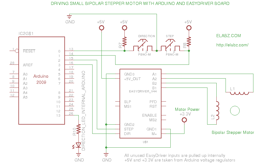
A video and the circuit with schematics for connecting and controlling the world's smallest linear actuator based on a bipolar stepper motor from a Blu-ray drive. The project involves the design and implementation of a circuit to control a linear...
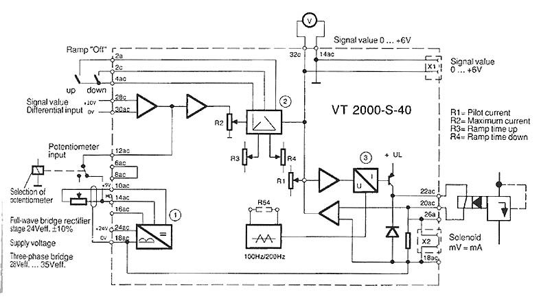
The function is to adjust the time constant associated with a capacitor, thereby influencing the ramp time. The components involved include a transistor, capacitor, and resistor. The circuit described is designed to modify the time constant in an RC (resistor-capacitor)...
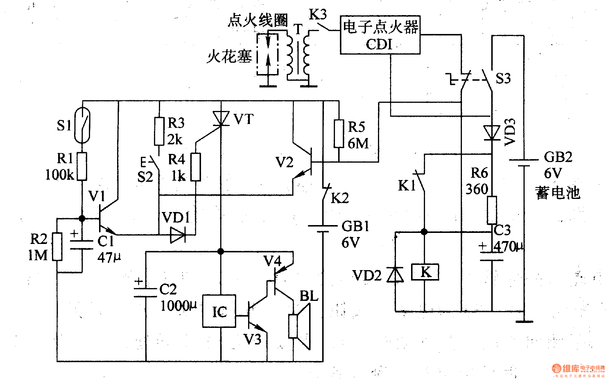
The multi-function motorcycle anti-theft alarm discussed in this article is suitable for anti-theft applications for all two-wheel motorcycles. The motorcycle anti-theft alarm circuit consists of a mobile delay alarm circuit, an ignition switch ground wire break alarm circuit, and...
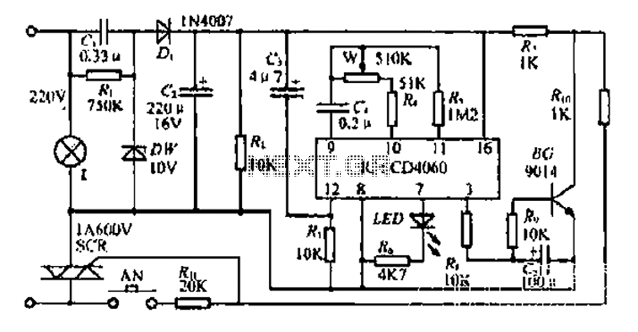
The circuit includes a CD4 component with a connection of 16 feet for the Vcc terminal, 8 feet for the ground, 12 feet for the reset terminal, 7 feet for the Qt end, and 3 feet for the Q...
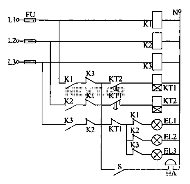
Any power supply and distribution sector should include phase sequence detection to ensure that the power supply phase sequence remains stable and unchanged. Additionally, any irreversible electromechanical product should also incorporate phase sequence detection to verify the phase sequence...
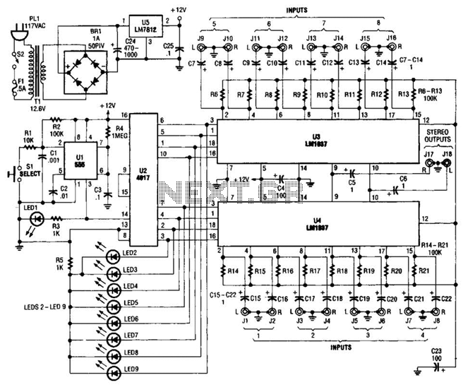
This source is selected by pressing a momentary-contact pushbutton switch (SI). Switch SI is connected to the trigger of a 555 oscillator/timer (U1) configured as a monostable multivibrator, which generates one short output pulse for each press of SI....