
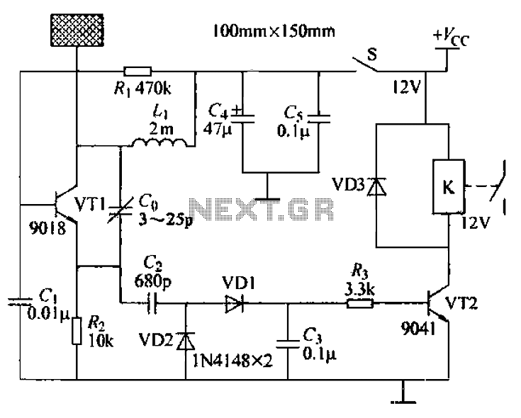
Integrated static switch circuit diagram of the flip-flop TDA1024

The described circuit utilizes an integrated circuit (IC) TDA1024, which serves as a trigger mechanism for controlling a thyristor-based load. The operation begins with the closure of switch S, which is contingent upon the activation of the TDA1024. The zero crossing of the mains voltage is critical in this design, as it generates a trigger pulse that initiates the conduction phase of the bidirectional thyristor. This allows full current to flow through the load resistor Rl, effectively powering the connected device.
To ensure safe operation, especially during the turn-off phase, the circuit design incorporates a protective varistor in parallel with the triac. This component plays a vital role in suppressing voltage spikes that could potentially damage the thyristor during abrupt changes in load conditions or external disturbances.
The circuit is designed to accommodate various power levels depending on the type of thyristor used. With the BT139 thyristor, the circuit can handle a maximum output power of 1400W. For applications requiring higher power, the BTW41 thyristor can be employed, allowing for an output power of up to 2000W. For even more demanding applications, the circuit can support a thyristor capable of handling up to 5000W, ensuring versatility in various industrial and consumer applications.
The overall schematic design reflects a robust approach to controlling AC loads with precise timing and protection features, making it suitable for a wide range of electrical applications.Circuit switch S is closed after the integrated circuit TDA1024 trigger is turned on. Whenever the zero crossing of the mains voltage generates a trigger pulse, bidirectional thyristor, full current flowing through the load Rl. When the switch S OFF no load current. To protect the Triac in parallel across its varistor. The maximum output power of the circuit is a 1400W, such as the use of thyristor BT139, output power up to 2000W, the use of BTW41, output power up to 5000W.
Related Circuits
1999 Honda Civic Fuel Injector Wiring Diagram. The fuel injector wiring diagram for the 1999 Honda Civic outlines the electrical connections and components involved in the fuel injection system. This diagram is essential for troubleshooting and repairing issues related to...
Are you unfamiliar with the basics of electronics? An online store has recently opened, offering four excellent books on basic electronics for sale. Reviews of these books are available, and purchases can be made as desired. These books are...
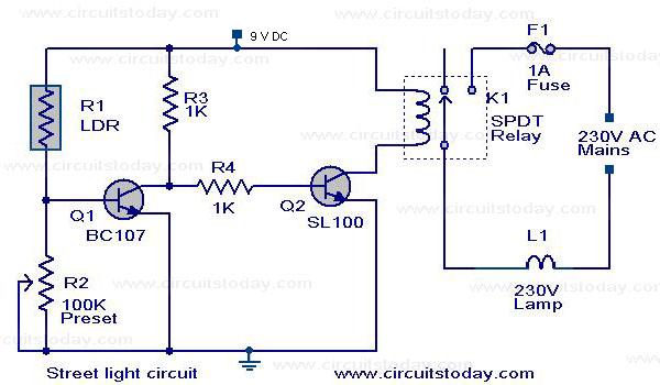
A street light that automatically switches ON when night falls and turns OFF when the sun rises. The circuit uses an LDR to sense the light. The automatic street light circuit functions by utilizing a Light Dependent Resistor (LDR) as...
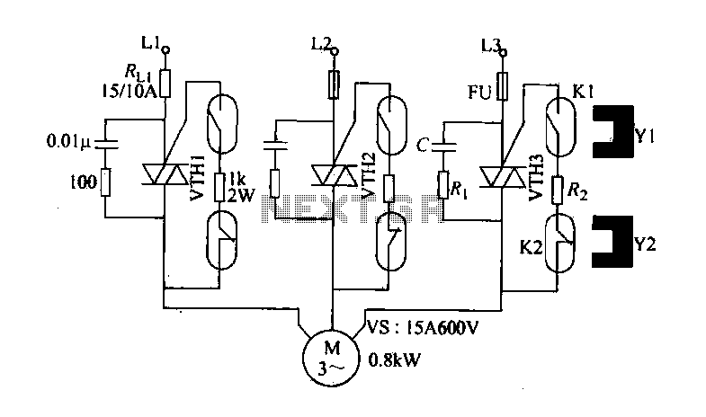
The circuit diagram illustrates a female textile machine power control circuit. VTH1-VTH3 represent TRIACs, while R and C form the absorption line. Rz serves as the triggering current limiting resistor. K1 is designated for starting the reed, and K2...
A capacitive proximity controller typically consists of a radio frequency oscillation circuit and a detection plate. The circuit is constructed using discrete components for capacitive proximity sensing detection. The transistor VT1, along with surrounding components, forms a radio frequency...
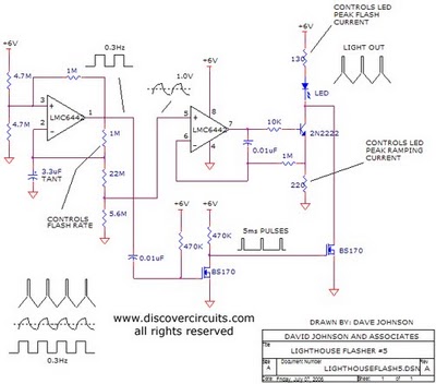
The aboriginal accessory forms a typical oscillator circuit that produces both a triangle waveform signal and a square wave signal. The triangle signal is fed into a voltage regulator circuit, which converts the triangle voltage signal to a triangle...