
relay circuits

The circuit design involves integrating a 12-volt air compressor with dual air horns, necessitating careful consideration of power management and physical installation. The use of an "L" bracket structure allows for a secure mounting of the horns while maintaining access to other components. The selection of mending plates for bracket fabrication provides a robust solution for horn attachment, ensuring stability during operation.
The relay serves as a critical component in the circuit, allowing high-current horns to operate without overloading the existing horn switch. The relay's terminals, though small, must be correctly identified and connected to ensure reliable operation. The relocation of the relay might be necessary depending on the available space, thus highlighting the importance of a flexible installation approach.
The use of ethafoam around the compressor not only dampens vibrations but also serves as a protective barrier against potential damage, emphasizing the importance of physical protection in electronic installations. The routing of the fuel line and tubing must be executed with care to prevent leaks and ensure efficient operation of the air horns. The inclusion of inline fuses is a standard practice in automotive and motorcycle circuits, providing an additional layer of safety by preventing potential damage from short circuits.
Overall, this installation requires attention to detail in both the mechanical and electrical aspects, ensuring that the final assembly operates efficiently and safely within the vehicle's existing framework. Proper adherence to the provided wiring diagram and careful handling of components will yield a successful integration of the air horns and compressor into the motorcycle's electrical system.Remove the 6 mm screw holding on the lower rear fairing cover. This is the black plastic piece the spark plug protectors are attached to. Do not remove the lower rear fairing covers, only the machine screw. Fabricate "L" brackets from the mending plates to mount your horns. I bent my mending plates in a vice and enlarged a couple of the holes to f it the 6 mm machine screws I used. Mount the horns on the "L" brackets with fittings supplied in the Fiamm Horn kit and mount the "L" brackets on the inside of the lower fairing covers to the back of the 6x30 mm machine screws. Mount the shorter air horn on the left front side (to leave more room for the relay which also get installed on the left front side) and the longer one on the right front side.
Secure the brackets in place with washers, lockwashers and nuts. Cut a piece of ethafoam the height of the 12 volt air compressor. Split the foam and wrap it around the compressor. Secure with duct tape if you like. The purpose of the foam is two fold. It helps to protect the 12 volt air compressor housing from vibration and scratching of the frame down tube. Identify the terminals on the 12 volt relay supplied in the Fiamm Air Horn Kit. Because the horns draw a lot more power (8 amps) than the stock horns we need to use a relay to switch battery power directly to the horns.
This will save wear and tear on the horn switch. Identifying the terminals on the 12 volt relay may require a magnifying glass because they are very small and etched on the black plastic housing of the relay adjacent to the pins. Mount the relay with the bolt that was used to secure the left front horn. If there is insufficient clearance when you re-install the lower left fairing you may have to relocate the relay slightly towards the rear of the bike.
I relocated my relay and secured it using a cable tie. Route the fuel line from the 12 volt air compressor to the "Y" fitting provided in the horn kit. Route the tubing from the "Y" fitting to each of the horns. Use the small hose clamps to secure the fuel line tubing at all connections. Put a solderless terminal connector on one end of the in line fuse holder. Connect the other end of the fuse holder to the 14 gauge wire using a butt connector. You will be connecting the terminal connector to the positive terminal of the battery. Remember to place the in-line fuse as close to the battery as possible for best protection. Route the two wires to the front of the bike in the vicinity of the relay switch and 12 volt air compressor and connect them using solderless connectors following the directions in the attached wiring diagram. This is important: The wiring diagram shown on the Fiamm Air Horn package will not work on our bikes.
It took some time before I found out the solution. Follow my solution in the wiring diagram exactly. This is important too: When I removed the wires from the stock horns there was a 🔗 External reference
Related Circuits
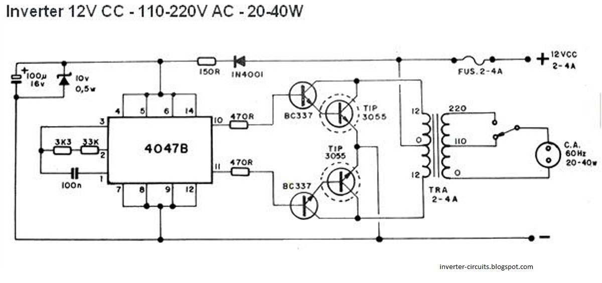
This schematic represents a simple 40W inverter that converts 12V to 220V. It has been functional for four years. The core component of the circuit is a CD4047 integrated circuit (IC) configured as an astable multivibrator. The resistance and...
This circuit is basically a resistance sensing window switch, except that the resistor takes the form of an NTC thermistor and the circuit thus responds to temperature. TH1 must have a resistance in the range 500 ohm - 9...
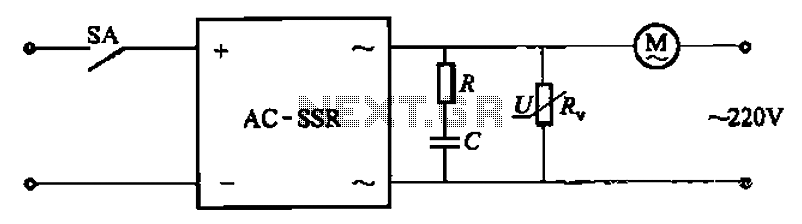
The circuit illustrated in Figure 3-13 is an RC surge absorption circuit that includes a resistor (R) and zinc oxide varistors (such as MY31, MYH12, MYH20 types, etc.), which serve as an overvoltage protection device. The resistance R is...
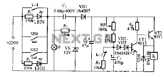
The lamp relay delay circuit is illustrated in Figure 7. Components S131 and SB2 are light buttons mounted in different locations. The lamp can operate with F. LEDs (LED1 and LED2) should be installed in SB1 and SB2 to...
When a network needs to transfer small blocks of information over long distances, RS-485 is often the preferred interface. Network nodes can include PCs, microcontrollers, or any devices capable of asynchronous serial communications. Compared to Ethernet and other network...
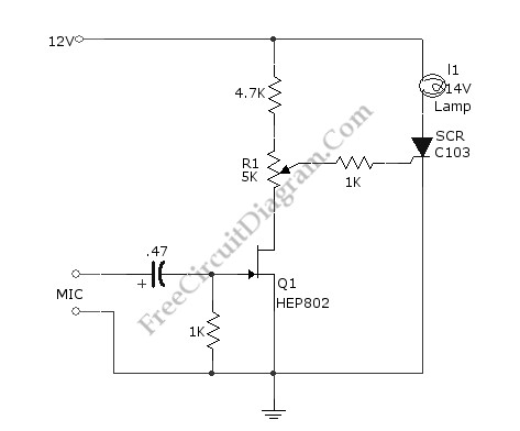
This simple circuit illustrated in the schematic diagram activates the switch using sound. It can be utilized for various applications, such as automatic (sound-controlled) disco lights or car LED light shows. The transistor Q1 amplifies the audio from the...