
Interfaces For The Remote-Control Transmitter Circuit

The interface circuits serve as versatile solutions for integrating remote-control functionality across various applications.
Circuit A utilizes the TA7343 Phase-Locked Loop (PLL) to decode frequency-modulated stereo signals. The open-collector output facilitates direct connection to a load, allowing for the efficient operation of connected devices. This configuration is particularly advantageous for applications requiring minimal component count while maintaining reliable signal processing.
Circuit B employs an optoisolator, specifically designed to provide electrical isolation between the control and output sides, enhancing safety and reducing the risk of noise interference. The optoisolator output drives a 12-V relay coil through a general-purpose transistor, enabling the control of higher voltage devices while protecting the low-voltage control circuit. This arrangement is commonly used in automation systems where isolation is critical.
Circuit C features an N-channel power MOSFET, which is controlled by the output of a 4N33 optoisolator. This configuration allows for efficient switching of high current loads, making it suitable for applications where rapid switching and high efficiency are required. The use of the 4N33 ensures that the control signal remains isolated from the power circuit, thus safeguarding sensitive components.
Lastly, Circuit D implements a toggle flip-flop mechanism, providing a simple yet effective means of achieving push-on/push-off control. This circuit can be utilized in various applications, such as lighting control or motor operation, where the user requires a straightforward method to toggle the state of a device without the need for multiple switches or complex logic.
Overall, these interface circuits exemplify practical solutions for integrating remote-control capabilities, addressing the needs for reliability, safety, and user-friendly operation in electronic designs. Shown here arc several possible interface circuits that can be used with the remote-control transmitter. The one in A illustrates a typical FM stereo MUX decoder with a load connected directly to the open-collector output of a TA7343 PLL.
The circuit in illustrates an optoisolator- coupler output driving a 12-V relay coil via a general-purpose transistor. C shows the gate of an N-channel power MOSFET connected to the output of a 4N33. The final circuit, D, is a toggle flip-flop that allows push-on/push-off control.
Related Circuits
Hi-fi headphones possess a wide frequency response and low distortion, making them incomparable to desktop Hi-Fi audio systems, particularly when compared to some branded headphones and even high-quality speakers. High-fidelity headphones are designed for music listening, offering high resolving...
PWM waveforms are widely utilized to regulate the speed of DC motors. The duty cycle of the digital waveform can be established either through an adjustable analog voltage level (as seen in a NE555-based PWM generator) or through digital...
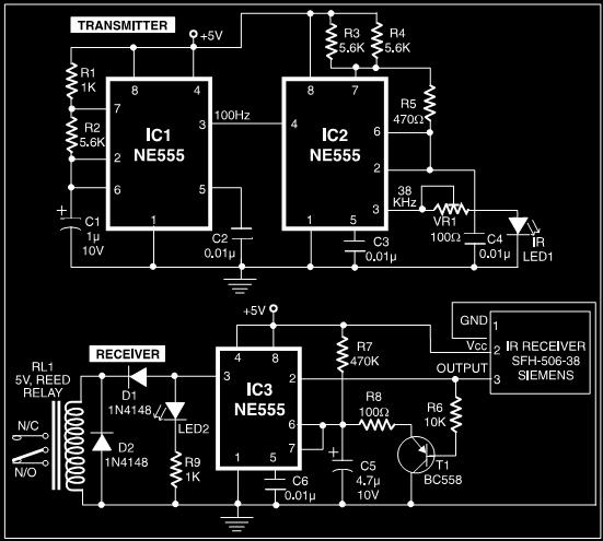
This post discusses a proximity detector circuit primarily utilizing the NE555 integrated circuit (IC). The circuit is designed for burglar alarms based on beam interruption, with the advantage that the transmitter and receiver are contained within the same enclosure,...
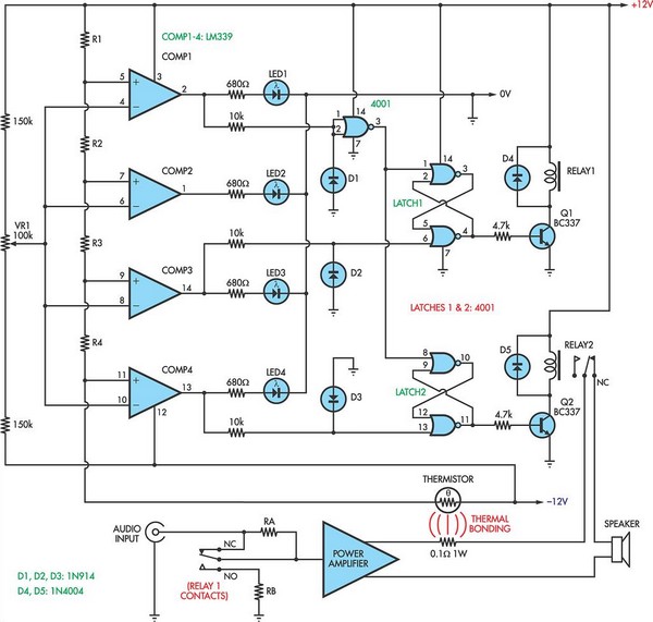
When the voltage on the non-inverting input of each comparator exceeds the voltage at its inverting input, the output transitions to a high state, activating the corresponding LED. NOR gate latches are connected to the outputs of the third...
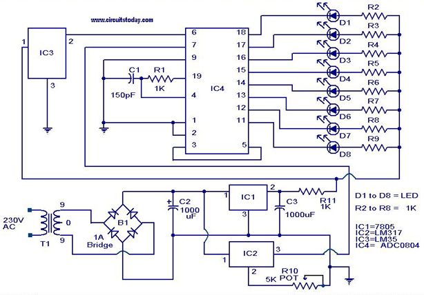
A digital temperature sensor circuit is explained with a circuit diagram. ICs ADC 0804, LM35, and LM317 are used in this digital circuit project. The digital temperature sensor circuit utilizes three primary integrated circuits (ICs): the ADC 0804, LM35, and...
This regulated power supply can be adjusted from 3 to 25 volts and is current limited to 2 amps as shown, but may be increased to 3 amps or more by selecting a smaller current sense resistor (0.3 ohm)....