
interfacing keyboard

The 4x4 matrix keyboard circuit consists of 16 keys arranged in 4 rows and 4 columns, allowing for efficient use of microcontroller pins. The microcontroller's GPIO (General Purpose Input/Output) pins are divided into two groups: one for rows and another for columns. Each row pin is configured as an input, while each column pin is set as an output. This configuration enables the detection of button presses through a process known as scanning.
During operation, one column is driven low while the remaining columns are set high. The microcontroller then reads the state of the row pins. If a button connected to a grounded column and a specific row is pressed, the corresponding row pin will read low. This allows the microcontroller to identify which button has been pressed based on the combination of active column and row.
To address the issue of switch bounce, which can cause erroneous multiple readings when a button is pressed or released, a delay is implemented in the software after each key press detection. This delay allows the mechanical switch to settle, ensuring that subsequent readings are stable and accurate. The assembly source code provided in the accompanying documentation outlines the specific instructions required for key scanning and debounce management, facilitating the integration of the matrix keyboard into various embedded applications.Keyboard is a basic and essential element of an embedded or microcontroller system. For small and hobby projects a 4x4 (hex) matrix keyboard is sufficient. The keys in the matrix keyboard are arranged in a matrix arrangement in order to utilize the port pins of the microcontrollers efficiently. Here we can interface 16 keys by using just 8 pins of microcontroller. This is shown in the circuit diagram. As shown in the circuit diagram, the rows are connected to 4 pins of a port, the columns are connected to other four pins, we configure rows as input and columns as output. By grounding one column and setting high all other columns, now by observing the status of the rows, we can come to know which button is pressed.
For example, if we ground the first column and if the first row is low, then the first button is pressed. We know that microcontrollers are really fast, therefore they can detect the key press in microseconds, if we hold the switch for long time (for a microcontroller long time is in milliseconds), the microcontroller is triggered more than once, also there is a problem of switch debounce because of the spring action of the switch.
To eliminate these problems we should introduce some amount of delay after every key press. The assembly source code for the circuit is given in the table below. 🔗 External reference
Related Circuits
Over time, microcontrollers have become increasingly powerful, cost-effective, and compact. A typical microcontroller from the past may have had 40 pins and lacked internal memory, whereas modern J-series PICs feature 96K of program memory and only 28 pins. This...
The TMS320C5505 Evaluation Board is specifically designed for developers in the DSP field as well as for beginners. The kit is structured in such a way that all possible features of the DSP can be easily utilized by everyone....
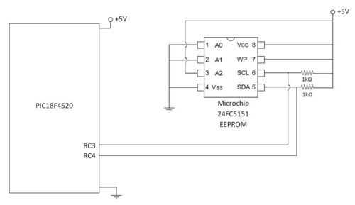
An external EEPROM is beneficial for various applications as it provides significantly more storage capacity than the internal memory of the 18F4520 microcontroller. Additionally, EEPROM retains its data even when power is disconnected. This project involves interfacing with a...
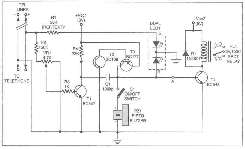
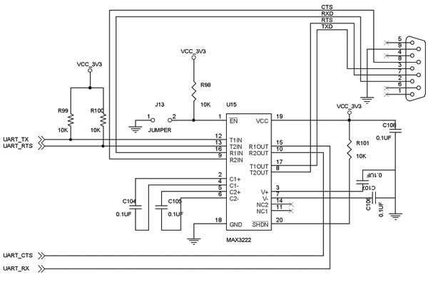
This add-on device for telephones can be connected in parallel to the telephone instrument. The circuit provides audio-visual indication of on-hook, off-hook, and ringing modes. It can also be used to connect the telephone to a CID (caller identification...
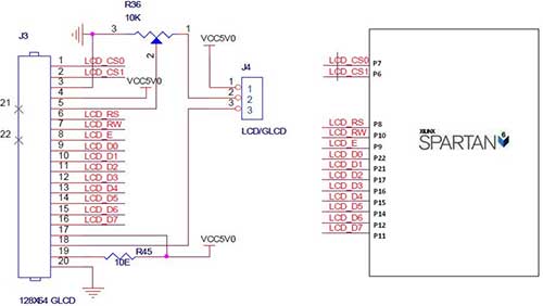
The Spartan-6 board features a 2x16 LCD, as illustrated in the accompanying figure. This 2x16 character LCD interface card supports both 4-bit and 8-bit modes, and it includes a facility for contrast adjustment via a trim potentiometer. In the...

An 8051 program must interact with external devices that facilitate communication with users. One of the most prevalent devices connected to an 8051 microcontroller is an LCD display. Common types of LCDs used with the 8051 include 16x2 and...