Telephone line interfacing
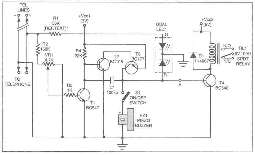
This add-on device for telephones can be connected in parallel to the telephone instrument. The circuit provides audio-visual indication of on-hook, off-hook, and ringing modes. It can also be used to connect the telephone to a CID (caller identification device) through a relay and also to indicate tapping or misuse of telephone lines by sounding a buzzer. In on-hook mode, 48V DC supply is maintained across the telephone lines. In this case, the bi-colour LED glows in green, indicating the idle state of the telephone. The value of resistor R1 can be changed somewhat to adjust the LED glow, without loading the telephone lines. In on-hook mode of the hand-set, potentiometer VR1 is so adjusted that base of T1 (BC547) is forward biased, which, in turn, cuts off transistor T2 (BC108). While adjusting potmeter VR1, ensure that the LED glows only in green and not in red. When the hand-set is lifted, the voltage drops to around 12V DC. When this happens, the voltage across transistor T1's base-emitter junction falls below its conduction level to cut it off. As a result, transistor pair T2-T3 starts oscillating and the piezo-buzzer starts beeping (with switch S1 in on position). At the same time, the bi-colour LED glows in red. In ringing mode, the bi-colour LED flashes in green in synchronisation with the telephone ring. A CID can be connected using a relay. The relay driver transistor can be connected via point A as shown in the circuit. To use the circuit for warning against misuse, switch S1 can be left in on position to activate the piezo-buzzer when anyone tries to tap the telephone line. (When the telephone line is tapped, it's like the off-hook mode of the telephone hand-set.) Two 1.5V pencil cells can provide Vcc1 power supply, while a separate power supply for Vcc2 is recommended to avoid draining the battery. However, a single 6-volt supply source can be used in conjunction with a 3.3V Zener diode to cater to both Vcc2 and Vcc1 supplies.
The circuit described functions as a telephone add-on device that enhances the standard telephone's capabilities by providing visual and audible feedback for different operational states. The device is designed to connect in parallel with the existing telephone line, ensuring that it does not interfere with normal telephone operations.
In the on-hook state, when the telephone is idle, the circuit maintains a 48V DC supply across the telephone lines, which powers the bi-colour LED to glow green, indicating that the telephone is ready for use. The resistor R1 is adjustable, allowing for fine-tuning of the LED brightness without adversely affecting the telephone line's load.
The operational state changes when the telephone handset is lifted. This action results in a voltage drop to approximately 12V DC, which causes the base-emitter junction of transistor T1 (BC547) to become reverse biased. Consequently, this turns off T1, leading to the activation of transistors T2 (BC108) and T3, which initiate an oscillation that drives the piezo-buzzer, producing an audible beep. During this state, the bi-colour LED switches to red, providing a clear visual indication that the telephone is in use.
In ringing mode, the circuit is designed to synchronize with the incoming ringing signal, causing the bi-colour LED to flash green in rhythm with the ring, thus alerting users to incoming calls. The integration of a caller identification device (CID) is facilitated through a relay that can be activated by a relay driver transistor connected at point A in the schematic.
To enhance security, the circuit includes a feature to detect unauthorized tapping of the telephone line. By keeping switch S1 in the "on" position, the piezo-buzzer will sound if the line is tapped, mimicking the off-hook condition.
Power supply considerations include the option of using two 1.5V pencil cells for Vcc1, while a separate power source for Vcc2 is advised to prevent battery depletion. Alternatively, a single 6V supply can be employed, using a 3.3V Zener diode to regulate the voltage for both power supply requirements, ensuring stable operation of the device.
Overall, this add-on circuit significantly enhances the functionality of a standard telephone by providing essential indicators for its operational status and security features against misuse. This add-on device for telephones can be connected in parallel to the telephone instrument. The circuit provides audio-visual indication of on-hook, off-hook, and ringing modes. It can also be used to connect the telephone to a cid (caller identification device) through a relay and also to indicate tapping or misuse of telephone lines by sounding a buzzer. In on-hook mode, 48V dc supply is maintained across the telephone lines. In this case, the bi-colour led glows in green, indicating the idle state of the telephone. The value of resistor r1 can be changed somewhat to adjust the led glow, without loading the telephone lines.
In on-hook mode of the hand-set, potentiometer vr1 is so adjusted that base of t1 (bc547) is forward biased, which, in turn, cuts off transistor t2 (bc108). While adjusting potmeter vr1, ensure that the led glows only in green and not in red. When the hand-set is lifted, the voltage drops to around 12V dc. When this happens, the voltage across transistor t1s base-emitter junction falls below its conduction level to cut it off.
As a result transistor pair t2-t3 starts oscillating and the piezo-buzzer starts beeping (with switch s1 in on position). At the same time, the bi-colour led glows in red. In ringing mode, the bi-colour led flashes in green in synchronisation with the telephone ring. A cid can be connected using a relay. The relay driver transistor can be connected via point a as shown in the circuit. To use the circuit for warning against misuse, switch s1 can be left in on position to activate the piezo-buzzer when anyone tries to tap the telephone line.
(When the telephone line is tapped, its like the off-hook mode of the telephone hand-set.) Two 1.5V pencil cells can provide Vcc1 power supply, while a separate power supply for Vcc2 is recommended to avoid draining the battery. However, a single 6-volt supply source can be used in conjunction with a 3.3V zener diode to cater to both Vcc2 and Vcc1 supplies.
🔗 External reference
