
interfacing lcd

The LCD (Liquid Crystal Display) operates based on specific control lines that dictate its behavior during data transmission. The Enable (EN) line is critical for signaling the LCD to process incoming data. The sequence begins with the EN line set low (0), indicating that the LCD is ready to receive data. After configuring the Register Select (RS) and Read/Write (RW) lines, the EN line is brought high (1) for a brief period (approximately 200 ns), allowing the LCD to latch the data before being returned to low (0).
The RS line determines the nature of the data being sent. When RS is low (0), the data is interpreted as a command, which could include operations like clearing the display or moving the cursor. When RS is high (1), the data represents characters that are to be displayed. This distinction is essential for proper communication with the LCD, as it dictates how the LCD interprets the incoming signals.
The RW line indicates the direction of data flow. A low (0) state signifies that data is being written to the LCD, while a high (1) state indicates that the LCD is being read. Most operations will involve writing commands to the LCD, with the RW line predominantly remaining low.
The LCD can function in two modes: 8-bit parallel mode and 4-bit mode. In 8-bit mode, a full byte of data is transmitted simultaneously, allowing for fast data transfer. Alternatively, in 4-bit mode, the data is divided into two packets of 4 bits, which can simplify the circuit design and reduce the number of required connections. The higher 4 bits are sent first, followed by the lower 4 bits.
Before the LCD can be used, it must undergo an initialization process. This involves sending specific commands to configure the display for operation. The first command sent should indicate that the data bus will operate in 4-bit mode, along with the selection of a 5x8 dot character font. This is accomplished by transmitting the hexadecimal command 20h. Following this, the command 0Fh is sent to enable the display and activate the cursor blinking feature, completing the initial setup for the LCD. Proper initialization is crucial for ensuring that the LCD functions correctly and displays the intended data.The EN line is called `Enable`. This control line is used to tell the LCD that you are sending it data. To send the data to the LCD, your program should make sure this line is low (0) and then set the other two control lines and/or put data on the data bus. When the other lines are completely ready, bring EN high (1) and wait for the minimum amoun t of time required ( about 200ns), and end by bringing it low(0) again. The RS line is the `Register Select` line. When RS is low(0), the data is to be treated as a command or special instruction (such as clear screen, position cursor, etc. ). When RS is high (1), the data being sent is text data which should be displayed on the screen. For example, to display the letter `T` on the screen you would set RS high(1). The RW line is the `Read/Write` control line. When RW is low (0), the information on the data bus is being written to the LCD. When RW is high (1), the program is effectively querying (or reading) the LCD. All commands are write commands except for 1 (`Get LCD status`), which is a read command. Thus, RW will almost always be low. The LCD can work in either 8 bit parallel mode, i. e, then entire 8 bit data can be sent at once, or it can be used in 4 bit mode. In 4 bit mode the 8 bit data is broken into packets of 4 bit data and sent (higher 4 bits first, then lower 4 bits).
4 bit mode simplifies the circuit. Before you may really use the LCD, you must initialize and configure it. This isaccomplishedby sending a number of initialization instructions to the LCD. The first instruction we send must tell the LCD we`ll be communicating with it with a 4-bit data bus (4-bit mode). We also need to select a 5x8 dot character font. These two options are selected by sending the command 20h ( `h` denotes hexadecimal format) to the LCD as a command.
We`ve now sent the first byte of the initialization sequence. The second byte of the initialization sequence is the instruction 0Fh. This commmand is sent to instruct the the LCD to, `Display on, Cursor Blinking`. 🔗 External reference
Related Circuits
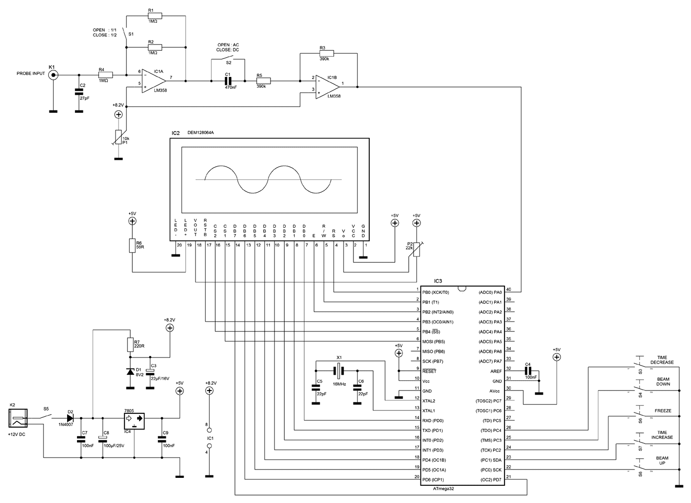
A few months ago as I was surfing on the net, I saw an oscilloscope based on PIC18F2550 microcontroller and a KS0108 controller based graphical LCD. That was Steven Cholewiak's web site. I had never seen before so amazing...
This project involves a USB interface for an alphanumeric LCD display, such as the 4x20 model, which can be controlled using the LCD Smartie program. The USB interface is implemented with the PIC18F2550 microcontroller and utilizes USB LCD modules....
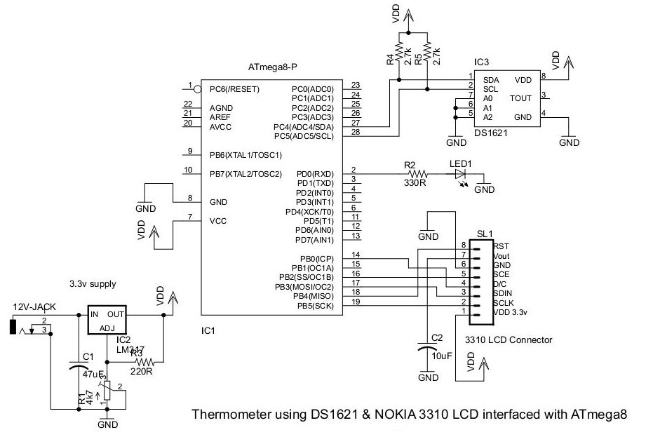
This document presents an application utilizing the Nokia 3310 LCD for designing a thermometer using the DS1621 temperature sensor IC. The DS1621 is an 8-pin sensor manufactured by Maxim. The circuit design involves integrating the DS1621 temperature sensor with a...
This multimeter is designed to measure output voltage and current in a power supply unit (PSU), with the current sense shunt resistor connected in series with the load at the negative voltage rail. It operates using a single supply...
Learn how to interface LEDs with the 8051 Microcontroller. Download free source code and circuit diagram of the P89V51RD2 Microcontroller. Interfacing LEDs with the 8051 microcontroller is a fundamental project that serves as an excellent introduction to microcontroller applications. The...
This project explains a very powerful frequency counter which has many useful software functions. The software can add or subtract 3 different IF frequencies (±455 kHz, ±10.7 MHz, and ±21.4 MHz). You have also two levels of resolutions, 1...