
interfacing of led wiht avr atmega16

```c
// CODE For Blink LED
#include <avr/io.h>
#include <util/delay.h>
int main(void) {
DDRC = 0xFF;
while(1) {
PORTC = ~PORTC;
_delay_ms(1000);
}
}
```
The circuit design for interfacing an LED with the ATMega16 microcontroller demonstrates a fundamental application of microcontroller technology in controlling output devices. The ATMega16 is a versatile 8-bit microcontroller from the AVR family, which is well-suited for educational and practical applications due to its simplicity and ease of programming.
In this design, the microcontroller's PORTC is configured as an output port by setting the Data Direction Register (DDRC) to 0xFF, which allows for all pins on PORTC to function as output. The green LED bar is connected to the output pins of PORTC, which will enable visual feedback through blinking.
The circuit includes a 10K resistor, which is commonly used to limit current and protect the LED from excessive current that could lead to damage. The 16uF capacitor serves to smooth any voltage fluctuations in the power supply, ensuring stable operation of the microcontroller and the LED.
The push button switch can be integrated into the circuit to allow user interaction, such as starting or stopping the LED blinking. However, the provided code currently does not utilize the push button functionality. The blinking is achieved through a simple loop that toggles the state of PORTC every second, creating a visual blinking effect. The use of the `_delay_ms(1000)` function introduces a one-second delay between toggles, ensuring that the LED bar remains on or off for a full second before changing state.
Overall, this circuit exemplifies the basic principles of microcontroller operation, including GPIO (General Purpose Input/Output) control, timing, and the integration of passive components for circuit stability.Interface an LED with AVR (ATMega16). Here I am using only one AVR microcontroller ATMega16, one register(10K), one capacitor(16uF/25v), One push button switch, Led BAR Green in stead of 8 led`s, power supply of +5v and -5v. Make the circuit as in diagram. Below is the circuits diagram and code for blink of the led will given below: // CODE For Blink LED using AVR-ATmega16 #include
Related Circuits

Numerous white LED driver circuits are available, with a well-known design called the Joule Thief capable of powering a single white LED from a 1.2V or 1.5V battery cell. Most of these circuits utilize one or two transistors to...
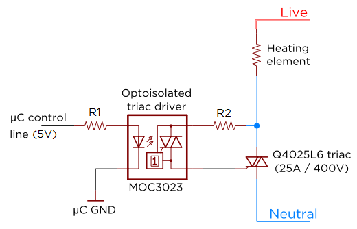
Several individuals have requested clarification on calculating resistor values for a triac circuit. This information may be beneficial for adapting the Sous Vader for custom builds. The circuit in question involves the resistor values R1 and R2 in an...
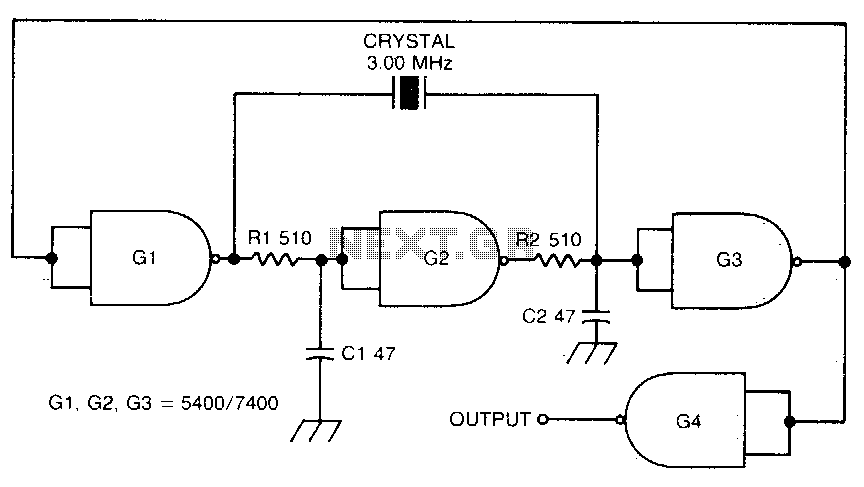
This circuit oscillates without the crystal. When the crystal is included in the circuit, the frequency will match that of the crystal. The circuit exhibits good starting characteristics even with low-quality crystals. This circuit design features a basic oscillator configuration...

A circuit provided by an LCD manufacturer illustrates the use of the POL signal from the display to derive the VCOM signal. It has been noted that LCD Bias ICs typically generate VCOM from a high bias voltage. The...

This is a simple toggle switch that can be operated through sound signals such as a whistle or clap. The output of the toggle remains either low or high until... This circuit utilizes a sound sensor to detect specific audio...
Various techniques demonstrate how enhanced PWM (pulse-width modulation) intensity control can be utilized in LED (light-emitting diode) drivers. PWM intensity control is a widely adopted method in LED driver circuits to regulate brightness levels. This technique involves modulating the width...