
Interior Convenience Light

The described circuit functions as a timer for the dome light in a vehicle or similar application, ensuring that the light remains illuminated for a specified duration after the door is closed. The timing mechanism relies on a resistor (R1) and a capacitor (C1), which together form an RC time constant. The time duration for which the dome light stays on is approximately calculated using the formula (1.1)R1 x C1, where R1 is the resistance in ohms and C1 is the capacitance in farads.
In practical implementation, when the door is closed, a switch is activated, allowing current to flow through R1 and charging C1. The charging of the capacitor will take time based on the values of R1 and C1. Once the capacitor is fully charged, the voltage across it will reach a threshold that turns off the circuit, thus extinguishing the dome light.
To design this circuit, it is essential to select appropriate values for R1 and C1 to achieve the desired delay. For instance, a larger resistor or capacitor will result in a longer illumination time, while smaller values will shorten the duration. It is also important to consider the maximum voltage rating of the capacitor and the power rating of the resistor to ensure reliable operation.
The circuit can be further enhanced with additional components such as a diode to prevent reverse current flow or a transistor to act as a switch for higher power applications. Proper layout and component selection will ensure that the circuit operates efficiently and meets the intended specifications for the dome light timing function. When the door is closed, this circuit keeps the dome light on for a period determined by Rl/Cl. The time is appr oximately (1.1)R1 x C1.
Related Circuits
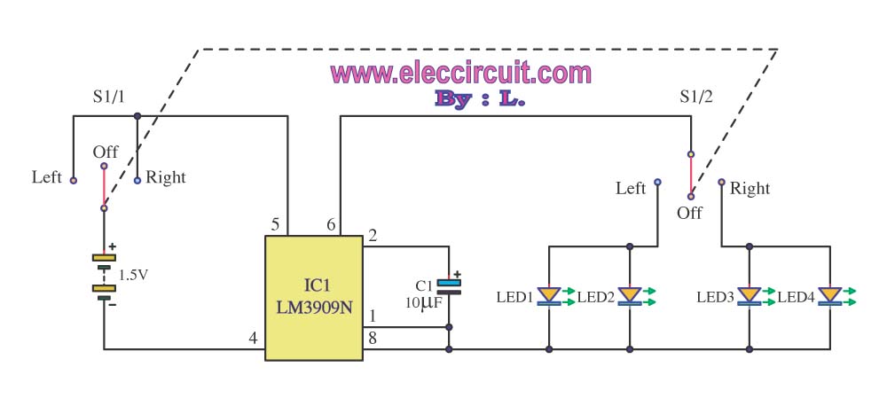
A bicycle typically does not have a turning light. When a cyclist wants to turn, it can be dangerous as vehicles following may not be aware of the turn. To enhance safety, a turning light circuit for bicycles can...
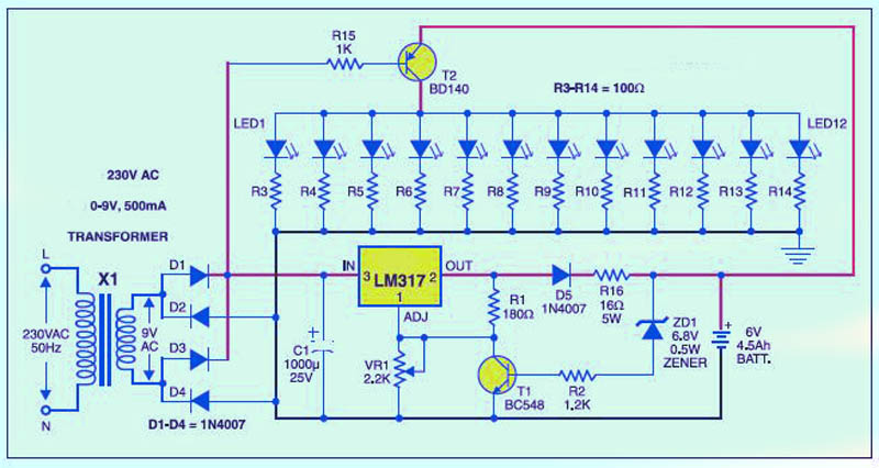
This is a low-cost circuit diagram for an emergency light utilizing a white LED. Components include an LM317 IC, a resistor, a transformer, an LED, and a variable resistor. The emergency light circuit using a white LED is designed for...
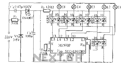
The Shenzhen Skywave Semiconductor Co., Ltd. produces a five-flash integrated circuit controller known as M1500P. This device is manufactured using a DIP 14 standard package and can be customized according to customer specifications for soft seal packaging. It operates...
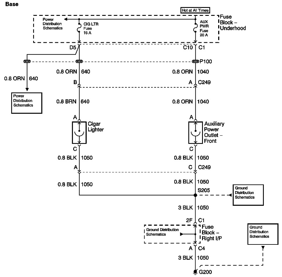
The provided information includes a fuse block diagram with the Auxiliary Power (Aux Pwr) fuse highlighted. It is advisable to check both sides of the fuse using a test light or multimeter to ensure functionality. It is assumed that...
The circuit employs two Light Dependent Resistors (LDRs) arranged in series with a separation of approximately half a meter. This configuration allows each LDR to detect the presence of a person entering or exiting the room. The processed outputs...
This project page has evolved into a design discussion. Constructive suggestions and collaboration are still welcome. Please refer to the comments section. The project focuses on the development of an electronic circuit design, which has transitioned from a simple project...