
Intermittent ozone generator circuit diagram using NE555

The circuit utilizes an adjustable resistor, RP1, to fine-tune the pulse duty cycle generated by integrated circuit IC2. This pulse duty cycle is critical as it directly influences the output pulse oscillation time of another integrated circuit, IC3. The oscillation time is a key factor in determining how long the ozone generator operates, which in turn affects the concentration of ozone produced in the air.
In practical terms, the adjustment of RP1 modifies the on-off duration of the pulses emitted by IC2. A higher duty cycle results in a longer 'on' time, increasing the operating time of the ozone generator, which leads to a higher concentration of ozone. Conversely, a lower duty cycle reduces the operating time, thus decreasing the ozone concentration.
This configuration is particularly useful in applications where precise control of ozone levels is necessary, such as in air purification systems or industrial processes that require specific ozone concentrations for optimal performance. The ability to adjust the duty cycle allows for flexibility in response to varying environmental conditions or specific operational requirements.
In summary, the circuit's design effectively enables the user to manipulate ozone generation through careful adjustment of the pulse duty cycle, ensuring that the desired air quality standards can be met consistently.Adjust the RP1, adjustable the IC2 pulse duty cycle to change IC3 pulse oscillation time, to regulate the the ozone generation time, thus achieving the purpose of changing the concentration of ozone in the air. 🔗 External reference
Related Circuits
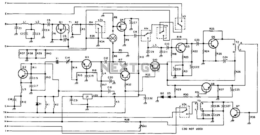
This 49-MHz FM transmitter comprises an audio amplifier, a low-pass filter, three RF stages, and a regulated DC power supply. The output power is approximately 16 mW into a 50-ohm load. This transmitter is suitable for various 49-MHz applications,...
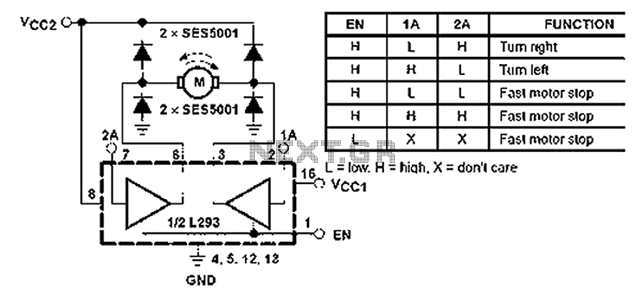
All inputs are compatible with TTL. Each output consists of a complete totem pole driver circuit, utilizing Darlington transistors and pseudo-Darlington sources. The driver enable signals, labeled as 1,2 EN and 3,4 EN, control the activation of drivers 1...
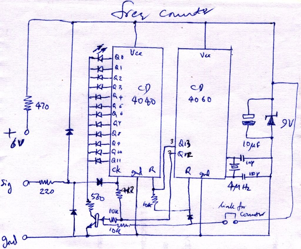
The construction is nearly complete, and a circuit diagram has been created. The design has been finalized and documented on paper. The circuit diagram represents a critical stage in the development of an electronic project, serving as a blueprint for...
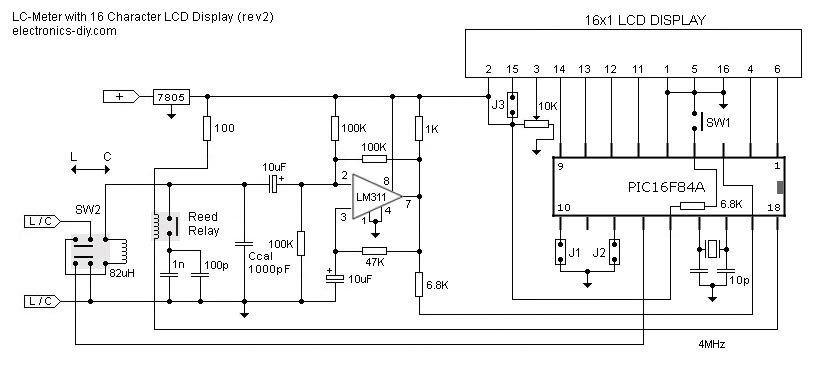
This is one of the most accurate and simplest LC inductance/capacitance meters available, which can be easily constructed by an individual. This LC meter is capable of measuring very small inductances ranging from 10 nH to 1000 nH, 1...
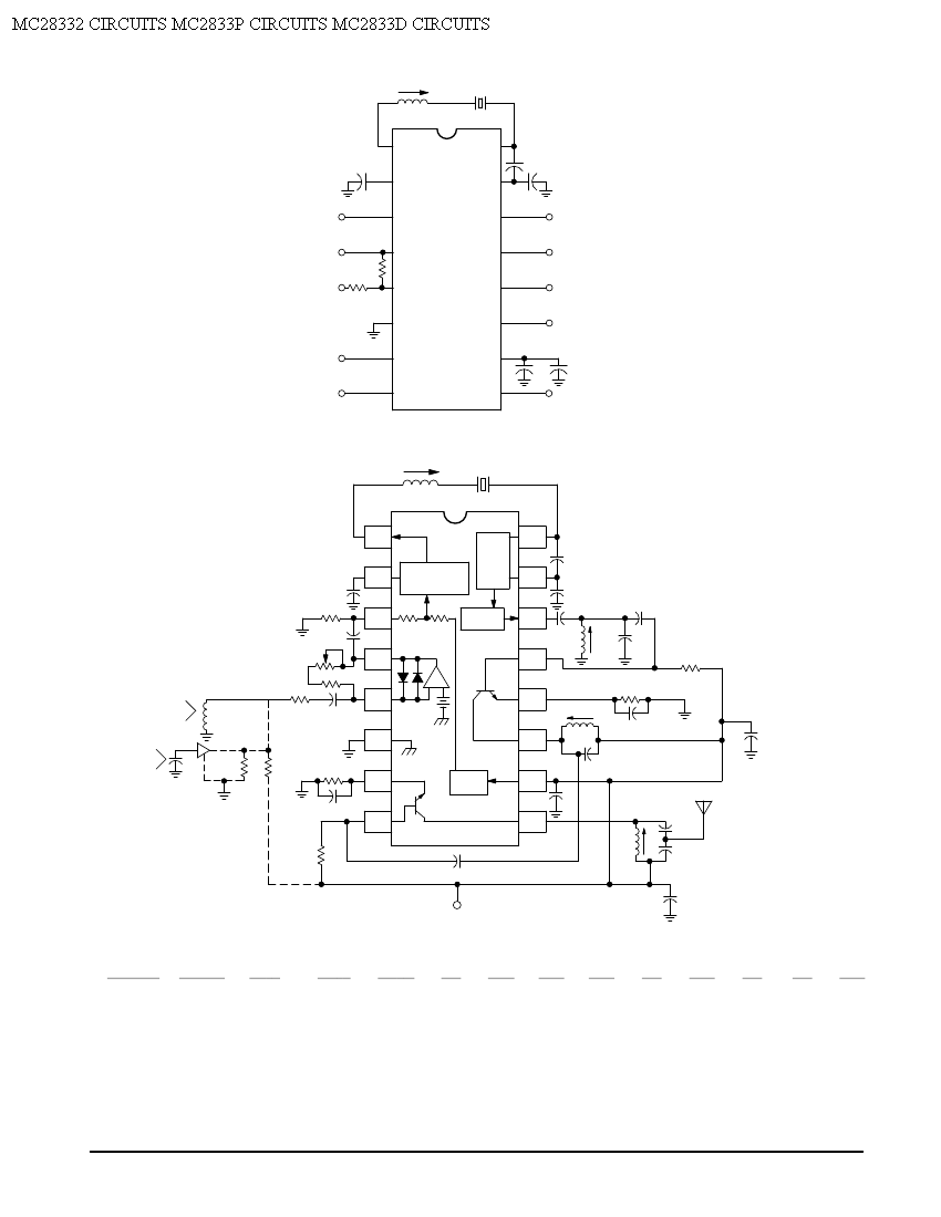
Crystal X1 operates in fundamental mode and is calibrated for parallel resonance with a load capacitance of 32 pF. The final output frequency is produced through frequency multiplication within the MC2833 integrated circuit (IC). The RF output buffer at...
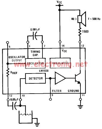
The LM1830 low-level detector can utilize an audio indication (speaker) or a visual indicator (LED - light-emitting diode) that activates when the level is too low. This low-level detector circuit generates a 500 Hz audio signal when the level...