
Two chip Frequency Meter with binary readout circuit

The circuit diagram represents a critical stage in the development of an electronic project, serving as a blueprint for the physical layout and interconnections of components. It typically includes various elements such as resistors, capacitors, transistors, and integrated circuits, which are essential for the intended functionality of the device.
The diagram should clearly indicate the connections between components, ensuring that the flow of current is accurately represented. Each component is usually labeled with its value or part number, facilitating easy identification during assembly and troubleshooting. Additionally, the power supply connections must be clearly marked to avoid any potential errors that could lead to circuit failure.
In a well-documented circuit diagram, the orientation of polarized components, such as electrolytic capacitors and diodes, must be specified to prevent incorrect installation. Furthermore, signal flow direction might be indicated with arrows, enhancing clarity for users who will implement the design.
Proper scaling of the schematic is also essential, as it allows for easier reading and understanding of the circuit's complexity. A legend or key may be included to explain any symbols used, ensuring that the diagram is accessible to individuals with varying levels of expertise.
Overall, a comprehensive circuit diagram not only aids in the construction process but also serves as an invaluable reference for future modifications or repairs. It encapsulates the design intent and functional requirements, forming the foundation for successful electronic project execution.Now, when the construction is nearly done, here is a circuit diagram. When I finally settled on how it was going to be done, and set it down on paper,.. 🔗 External reference
Related Circuits
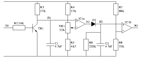
IC1 is a dual operational amplifier. In this circuit, each op-amp functions as a voltage comparator. When the voltage at the positive input exceeds the voltage at the negative input, the output transitions to a high state. Conversely, when...
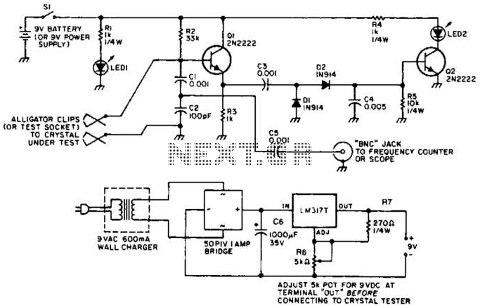
Q1 functions as a Colpitts crystal oscillator. If the crystal being tested is operational, the RF signal is rectified by diodes D1 and D2, which activates Q2 and illuminates indicator LED2. Additionally, LED1 serves as a power indicator. The circuit...
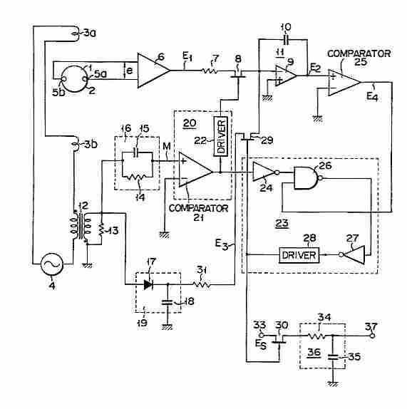
Electromagnetic flow meter: How to measure fluid flow using a magnetic field. An electromagnetic flow meter is a device used to measure the flow rate of conductive fluids by utilizing Faraday's law of electromagnetic induction. This principle states that when...
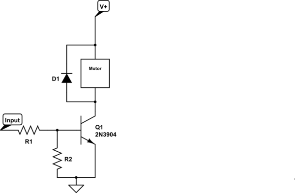
Control a small 5V motor using an external power supply by triggering a transistor with an Arduino. The transistor in use is an NPN type, specifically the 2N3904. To control a small 5V motor using an Arduino and an NPN...
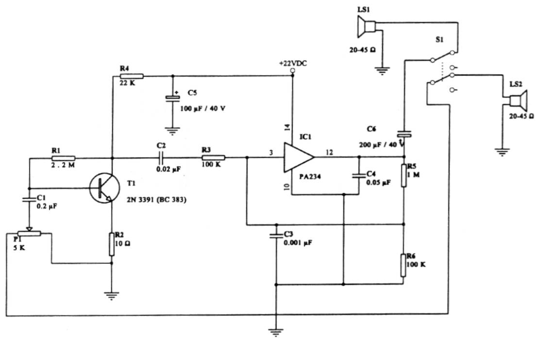
This intercom circuit is versatile and can be utilized in various applications. It operates at 22V, although it may function at a lower voltage (experimental testing is suggested). The circuit utilizes a loudspeaker with an impedance of 20-45 Ohms...
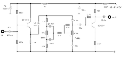
The first BC109C transistor functions as a buffer, delivering a high input impedance of approximately 250k and exhibiting a voltage gain marginally below unity. Given that the Baxendall tone control circuit operates passively, it attenuates all audio frequencies. The...