
Internal Resistance Tester For Batteries

This battery testing circuit utilizes two 555 timer integrated circuits (ICs) to effectively measure the internal resistance of lead-acid and gel cell batteries with capacities exceeding 20Ah. The primary function of the circuit is to switch a load of approximately 18A at a frequency near 50Hz, allowing for accurate measurement of the battery's internal resistance using a digital multimeter.
The configuration begins with IC1, which is set up as a monostable timer. Upon pressing switch S1, IC1's output at pin 3 transitions to a high state for a duration of 10 seconds. This output triggers IC2, which is configured as an astable oscillator operating at 50Hz. The output from IC2 drives the power MOSFET Q1, which is connected in series with a load formed by three 0.22Ω 50W resistors. The load is crucial for creating the necessary conditions to measure the internal resistance.
The circuit includes two LEDs for indication purposes: LED1 signals when the circuit is powered by a battery, and LED2 illuminates during the testing phase, providing visual confirmation of operation. While a thermostat is not mandatory for one-time use, it is recommended for repeated testing sessions to prevent overheating. The suggested thermostat, Jaycar ST-3823, should be rated for a temperature of 70 °C.
Thermal management is vital, particularly for the resistors and the thermostat, which should be mounted on an aluminum heatsink of at least 2mm thickness. The power MOSFET itself does not require additional cooling due to its operational characteristics in this application.
The internal resistance of automotive batteries typically ranges from 15mΩ to 3mΩ, a critical parameter that can influence battery performance. Prior to testing, it is essential to check the electrolyte levels in the battery and ensure that the terminal voltage exceeds 12.5V, indicating a near full charge. It is also advisable to measure the DC voltage across each battery post and its respective terminal while the headlights are activated; this voltage should be less than 10mV to confirm good connectivity. If the voltage exceeds this threshold, terminal cleaning is necessary to ensure accurate test results.
For the internal resistance measurement, the multimeter probes must be connected directly to the battery posts to obtain precise readings, avoiding any potential inaccuracies that may arise from measuring at the terminals. This setup provides a reliable method for assessing battery health and performance, enabling informed decisions regarding battery maintenance and replacement.This circuit is designed to check the condition of lead-acid and gel cell batteries with capacities greater than 20Ah. It switches a load of about 18A at a rate close to 50Hz so that the internal resistance of the battery can be measured using a digital multimeter across the battery terminals.
The measured AC voltage in millivolts divided by 10 (i e, a shift of the decimal point) is approximately equal to the battery`s internal resistance in milliohms. As shown, the circuit is quite straightforward and is based on two 555 timer ICs (IC1 & IC2) and power Mosfet Q1.
IC1 operates as a monostable timer with a period of 10s. When switch S1 (Test) is pressed, IC1`s pin 3 output goes high for 10s and this enables IC2 which operates as a 50Hz astable oscillator. IC2 in turn drives power Mosfet Q1 which is connected across the load in series with three 0. 22W 50W resistors. IC2 then turns off again after 10s - ie, at the end of the monostable timing period. LED1 provides power indication when the circuit is connected to a battery, while LED2 (green) comes on during the test period.
The thermostat is not necessary unless the unit is to be used repeatedly (the Jaycar ST-3823 70 °C unit is suitable) and you want to protect the output circuit against overheating. The power Mosfet does not need cooling but the thermostat and the 0. 22W 50W resistors should all be mounted on an aluminium heatsink at least 2mm thick. In practice, the internal resistance of car batteries can vary from about 15mW down to about 3mW. Before testing the battery, check that the electrolyte level is correct and that the voltage across its posts exceeds 12.
5V for a nominal 12V battery; ie, close to full charge. That done, switch on the car`s headlights and measure the DC voltage between each battery post and its connecting terminal. It should be less than 10mV in both cases; if not, the terminals need cleaning. Once you`ve done that, you can turn off the headlights, connect the tester and proceed with the internal resistance test.
Be sure to connect the multimeter`s test probes directly to the battery posts, to read the internal resistance (not the battery terminals). 🔗 External reference
Related Circuits
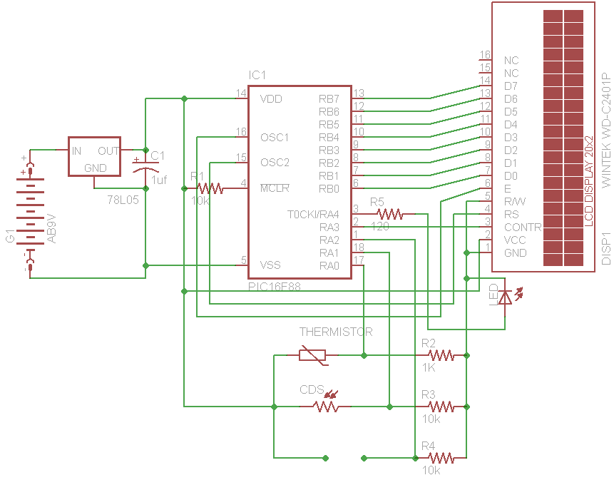
The initial concept for this project involves interfacing the WINTEK WD-C2401P LCD panel with a PIC microcontroller. The intention is to incorporate several ADC readings to provide useful information on the LCD. PORTB on the PIC serves as the...
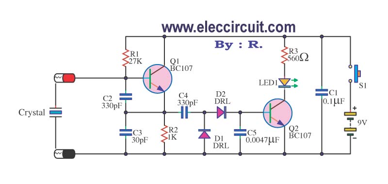
A multimeter cannot be used to test a crystal oscillator. Instead, a dedicated circuit is required, capable of checking crystals within the frequency range of 100 kHz to 900 MHz. This circuit is easy to construct and cost-effective. To construct...
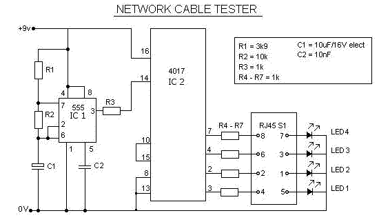
This is a multifunction RJ45 network cable tester designed for testing network cables (RJ45) and telephone cables (RJ11). It is cost-effective and user-friendly. The tester determines whether a network cable is a crossover or straight type by illuminating a...
A highly beneficial project involving a crystal tester circuit, also known as an xtal tester circuit, constructed with only a few components. The circuit forms an oscillator that will only oscillate if the crystal under test is functioning properly....
Also known as a megger insulation resistance meter, this device measures resistance at the megohm level. It is primarily used to assess the insulation resistance of motors, electrical circuits, and equipment. Additionally, it helps determine whether there is circuit...

Circuit characteristics: A simple phase shift range of 180 degrees, with a practical range of 170 degrees. The circuit is influenced by temperature and is suitable for small power applications in less demanding situations. The circuit operates by utilizing a...