
crystal tester circuit

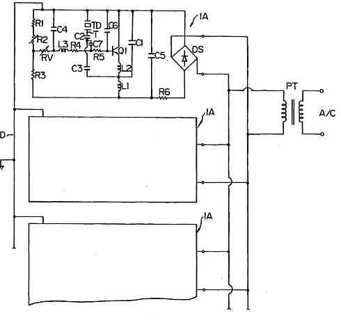
The crystal tester circuit operates on the principle of using a simple oscillator configuration, typically based on a transistor or an operational amplifier. The primary function of this circuit is to determine the operational status of a crystal oscillator by observing the oscillation output. In this design, the crystal under test is connected to the oscillator circuit. If the crystal is functional, it will allow the oscillator to generate a stable signal at its resonant frequency.
The output from the oscillator is a small AC voltage, which is then passed through a rectification stage utilizing 1N914 diodes. These diodes are chosen for their fast switching capabilities and are capable of handling the low voltage levels produced by the oscillator. The rectification process converts the AC signal into a pulsed DC signal.
Following rectification, the output is smoothed using a 0.1 µF capacitor, which acts as a filter to reduce voltage ripple and provide a more stable DC output. This filtered output can then be measured using a multimeter or an oscilloscope to ascertain the health of the crystal. If the crystal is defective, the oscillator will not produce any output, indicating that the crystal is not functioning correctly.
The simplicity of this circuit, requiring minimal components, makes it an excellent project for hobbyists and professionals alike. It serves as a practical tool for testing various crystal oscillators in electronic devices, ensuring that they are in good working order before installation or use. The compact design allows for easy integration into a larger testing setup or for standalone use.A very useful project of a crystal tester circuit or xtal tester circuit built with only few components the circuit form an oscillator that will only oscillate if the under test crystal is in good working condition and the oscillator output voltage will be rectified by 1N914 diodes and filtered by 0. 1uF capacitor and reach 🔗 External reference
Related Circuits
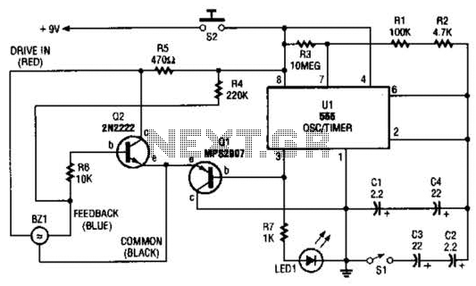
The electronic darkroom timer is constructed using a 555 oscillator/timer, a pair of general-purpose transistors, a buzzer, and an LED. The 555 timer (U1) is set up as an astable multivibrator, functioning as a free-running oscillator. The frequency of...
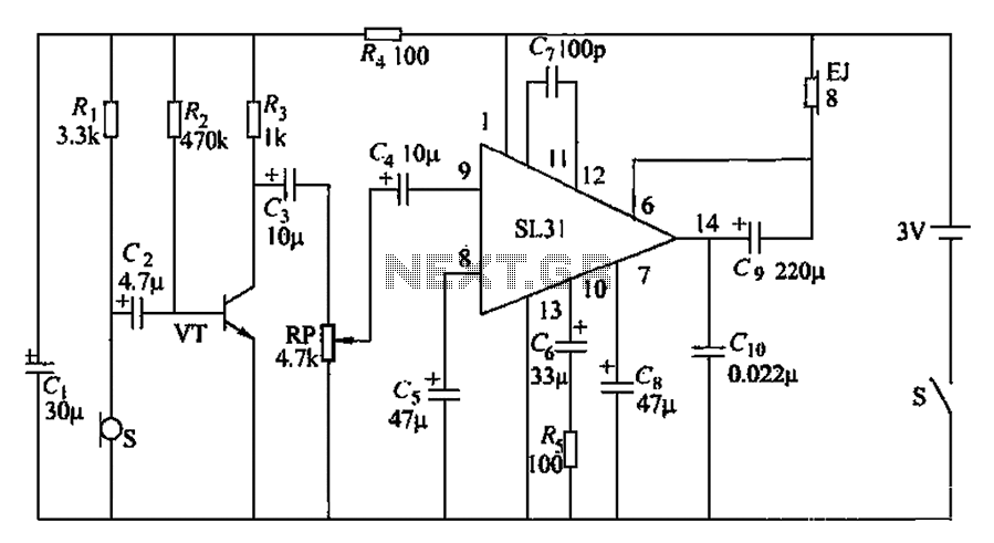
Bicycle tire leak detector circuit schematic. The circuit detects air leaks in car tires caused by sharp objects. It uses a microphone (BM) to capture the sound of escaping air, which is then converted into an electrical signal. This...
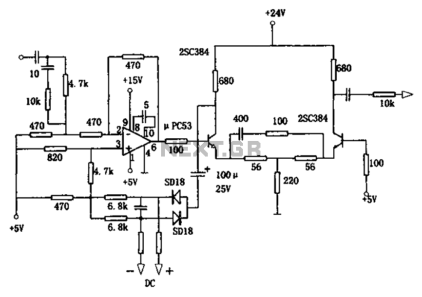
The circuit is designed for a broadband linear detection application with a bandwidth of 10 MHz. It serves as a millivoltmeter measuring instrument suitable for frequencies exceeding 10 MHz. The circuit features a linear detector utilizing operational amplifiers, specifically...
This is a 3 Band Equalizer circuit designed to control the treble, midrange, and bass frequencies. The circuit utilizes a single operational amplifier (op-amp). The 3 Band Equalizer circuit serves to enhance audio signals by allowing users to adjust specific...
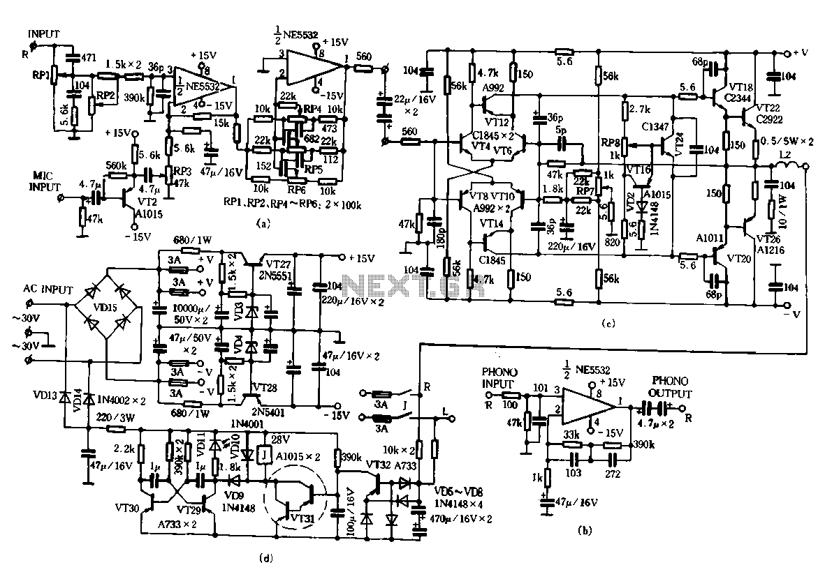
Only the R channel is shown, with the original reference PCB label. Figure (a) illustrates the front tone circuit, which consists of a common negative feedback operational amplifier in an RC circuit configuration. The microphone signal is amplified by...
Ultrasonic atomizer circuit: How to generate an atomized water mist using ultrasonic sound waves. The ultrasonic atomizer circuit is designed to produce a fine mist of water by utilizing ultrasonic sound waves. This process involves the conversion of electrical energy...