
Inverter as high voltage low current source

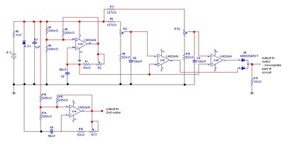
This circuit utilizes the 555 timer IC in astable multivibrator configuration to generate a square wave output, which is essential for driving a transformer. The frequency of oscillation can be adjusted by varying the values of the resistors and capacitor in the timing network. The output frequency must be optimized to match the resonant frequency of the transformer, ensuring efficient energy transfer and minimizing losses.
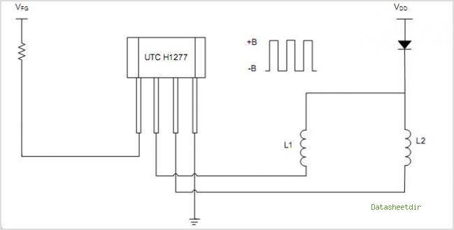
The output from the 555 timer is connected to a limiting resistor, which protects the circuit from excessive current that could damage the components. The primary coil of the transformer is connected in series with this resistor, allowing the magnetic field to build up when the output is high. The energy stored in the magnetic field is then transferred to the secondary coil of the transformer when the output switches low, leading to a reversal of current flow. This mechanism is critical for maintaining a continuous and efficient power supply to the connected devices.
Capacitor C3 plays a vital role in smoothing the output voltage and providing stability to the circuit. By selecting an appropriate capacitance value, the output can be made more symmetric, which is crucial for applications requiring precise voltage levels. The circuit's design allows for flexibility in component selection, enabling it to cater to various load requirements while ensuring reliable operation across different scenarios. Overall, this power supply circuit is well-suited for portable applications that demand efficiency and stability.The circuit is capable of providing power for portable Geiger counters, dosimeter chargers, high resistance meters, etc. The 555 timer IC is used in its multivibrator mode, the frequency adjusted to optimize the transformer characteristics.
When the output of the IC is high, current flows through the limiting resistor, the primary coil to charge C3. When the output is low, the current is reversed With a suitable choice of frequency and C3, a good symmetric output is sustained.
Related Circuits
The UTC H654 is an integrated Hall sensor with complementary output drivers designed for the electronic commutation of brushless DC fans. It consists of an on-chip Hall voltage generator, a differential amplifier Schmitt trigger, and an open-collector output all...
Many applications do not require the precision of a digital or analog (bar graph) indicator but still benefit from more than a simple low/high signal. An example is a battery charge level indicator in a car. This basic circuit,...
This circuit is beneficial for applications where a load must be activated from one location and deactivated from another. Multiple momentary normally open (N/O) switches or push buttons can be connected in parallel. The circuit described facilitates remote control of...

The circuit is a high-power car audio amplifier schematic. It functions as a car audio amplifier using the PA02 and LH0101 integrated circuits (ICs). Each IC delivers an output power of 30W with an 8-ohm impedance. The part list...
Noise in an amplifier circuit is intrinsically generated by each component within the circuit. Resistors, capacitors, and semiconductors all contribute to noise generation. Noise in an amplifier circuit can significantly affect performance and signal integrity. Each component, including resistors, capacitors,...
The goal is to control the speed of a 6-volt brush DC motor using a linear potentiometer and to create an oscillating speed effect, with the oscillation frequency also adjustable via a linear potentiometer. The desired complete cycle peak-to-peak...