
Voltage Controlled Oscillator

The circuit design involves controlling the speed of a 6-volt brush DC motor through variable resistance and modulation of pulse width. The use of a linear potentiometer allows for direct manipulation of the motor speed, while a second potentiometer facilitates the adjustment of the oscillation frequency. The oscillation effect is intended to create a throb-like behavior, with a cycle period adjustable between 1 to 5 seconds.
The sine wave generation can be accomplished using an oscillator circuit, which produces a continuous sine wave output. This output serves as a control signal for the pulse frequency modulation. A comparator or an operational amplifier can be employed to derive the pulse signal from the sine wave. The pulse width modulation (PWM) technique can be utilized to control the effective voltage applied to the motor, thus regulating its speed.
The challenge arises from the interaction between the sine wave voltage and the pulse width, causing the width of each pulse to shift relative to the amplitude of the sine wave. This can lead to undesirable motor behavior. To mitigate this issue, it may be beneficial to implement a Schmitt trigger after the sine wave output to create a clean square wave signal with well-defined transitions. This square wave can then be used to drive the motor without affecting the pulse width based on the sine wave voltage level.
Additionally, exploring the use of a microcontroller could provide a more flexible solution. A microcontroller can be programmed to generate PWM signals based on the sine wave input and the desired frequency settings, allowing for precise control over both speed and oscillation without the complications of analog components shifting pulse widths.
In summary, the circuit aims to achieve variable speed control of a DC motor with oscillation effects, leveraging potentiometers and waveform shaping techniques while addressing the challenges of pulse width modulation in relation to the sine wave control signal.I wish to control a DC motor speed for a 6 volt brush motor through a linear pot and also have that speed oscillate (throb) with the oscillation frequency controlled by a linear pot to have a complete cycle peak to peak of around 1 to 5 seconds. you can see the sine wave controlling the pulse frequency. The pulse frequency can be controlled seperate to the sine wave by a pot while being driven by the sine wave. hope that ain`t confusing :P I have an issue. the circuit I created to produce this frankenstein thingy, roughly works but shifts the width of each pulse MARK relative to the volatge in the sine wave. . and here is the completed circuit and do excuse my layout. I did my best to make it easy to read. I think there is some stuff that is not needed and also think there is stuff I need :P I could not for the life of me use another 555 timer to get the effect I want, that of a shifting pulse frequency relative to a sinewave.
So I used an OpAmp. If you have an alternative super simple method to have a pulse frequency shift relative to a sine wave without having the mark of each pulse peak shift it`s width relative to the voltage, I would love some thoughts. 🔗 External reference
Related Circuits
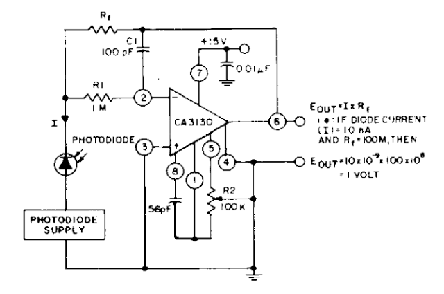
The photodiode current-to-voltage converter circuit employs three CA3130 BiMOS operational amplifiers, designed for applications that require sensitivity to sub-picoampere input currents. This circuit generates a ground-referenced output voltage that is directly proportional to the input current flowing through the...
A keyed power input connector, series rectifier and a shunt rectifier, both 1N4007, prevent reverse voltage from being applied to the power input. A 27 volt metal oxide varistor clamps the voltage to the 78L05 that follow it, to...
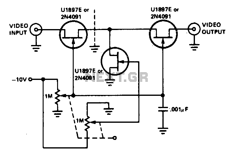
The tee attenuator offers optimal dynamic linear range attenuation of up to 100 dB, even at a frequency of 10.7 MHz with appropriate layout. The tee attenuator is a crucial component in RF and audio applications where signal integrity and...
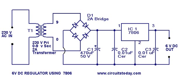
A simple 6-volt DC regulator circuit with a diagram and schematic using the 7806 IC, a positive voltage regulator. It serves as an elementary 6-volt, 1-ampere power supply circuit. The 7806 voltage regulator is a widely used integrated circuit that...
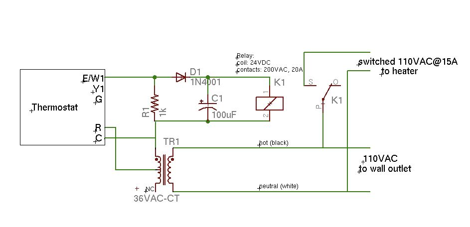
A basic schematic of the circuit is presented, marking the initial experience with Eagle software. It is important to note that only the W1 output of the thermostat is utilized, while C serves as the common connection. The schematic outlines...
This circuit utilizes small switching transistors, with a maximum motor drive current limited to approximately 250 mA at 5V. Testing has been conducted across a voltage range from 3V to 21V, and with certain component modifications, it may be...