
JFET Low Noise Preamp

Noise in an amplifier circuit can significantly affect performance and signal integrity. Each component, including resistors, capacitors, and semiconductors, introduces its own type of noise. Resistors primarily generate thermal noise, which is related to the temperature and resistance value. This noise is present even in the absence of an input signal and can be quantified using Johnson-Nyquist noise equations.
Capacitors, on the other hand, can introduce noise due to dielectric absorption and leakage currents, which can vary based on the type of dielectric material used. The noise generated by capacitors is typically less significant than that of resistors but can still impact low-noise applications.
Semiconductors, including transistors and diodes, contribute to noise through mechanisms such as shot noise and flicker noise (also known as 1/f noise). Shot noise occurs due to the discrete nature of charge carriers, while flicker noise is more pronounced at low frequencies and is related to imperfections in the semiconductor material.
To mitigate the effects of noise in amplifier circuits, careful selection of components is essential. Using low-noise resistors, capacitors with appropriate dielectric materials, and high-quality semiconductors can help reduce overall noise levels. Additionally, circuit design techniques such as proper grounding, shielding, and layout considerations can further minimize noise interference, ensuring that the amplifier operates effectively within its intended application.Noise, in amplifier circuit, is generated intrinsically by each components inside the circuit. Resistor, capacitor, and semiconductor generate noises. By.. 🔗 External reference
Related Circuits
The figures above illustrate the fundamental concept of a robot, which comprises input and output devices connected to a central processing unit, often referred to as the brain. In this case, the Arduino acts as the brain, controlling all...
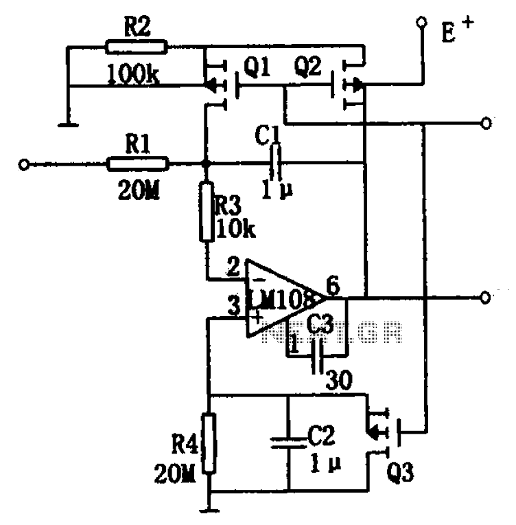
The integrator drift is minimal, not exceeding 500 V/s within the temperature range of -55°C to +125°C, as illustrated in the figure. The basic integrator is comprised of an operational amplifier, resistor R1, and capacitor C1. To enhance the...
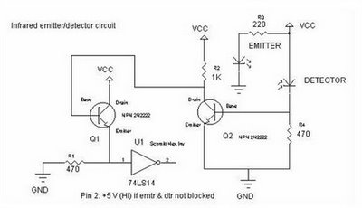
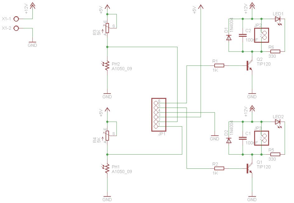
To achieve an optimal voltage swing, the resistance value of R1 must be selected with precision. The sensor resistance, Rsensor, equals a when there is no light exposure and b when light is present. The voltage difference between these...
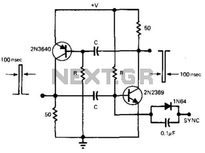
This simple and symmetrical free-running generator has a 50-ohm output impedance, a pulse width of 100 ns, and complementary outputs that swing from ground to the power supply voltage. It operates within a power supply range of less than...
The two circuits below illustrate the generation of low-frequency sine waves by shifting the phase of the signal through an RC network, ensuring that oscillation occurs when the total phase shift reaches 360 degrees. The transistor circuit on the...
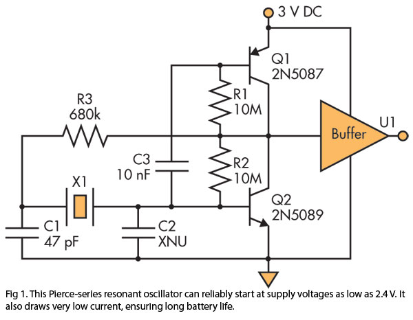
A Pierce (crystal) oscillator designed to deliver a stable clock signal for a minimum duration of one year when powered by battery voltages as low as 2.4 V. The Pierce oscillator circuit is a type of crystal oscillator that utilizes...