
inverter for household appliance

The inverter circuit design involves several key components and configurations that ensure efficient conversion of DC to AC power. The primary transformer winding is connected to the DC source, while the secondary winding outputs the AC voltage. The switching mechanism, composed of two transistors, operates in a push-pull configuration. Each transistor is biased to alternate the conduction state, ensuring that one transistor conducts while the other is off. This alternation creates the necessary AC waveform at the output.
To enhance performance, the biasing resistors can be fine-tuned. This adjustment allows for optimal switching times and minimizes power losses, which is critical in maintaining efficiency in the inverter operation. The choice of a transformer is crucial; a 5A/12-0-12 volt transformer is suitable for this application, providing the necessary voltage step-up when an oscillating signal is applied to its primary winding.
An oscillator circuit can be implemented using various components, including discrete transistors, integrated circuits like the 555 timer, or digital ICs. The oscillator generates the required 12V AC signal to drive the primary winding, and its frequency can be adjusted to match the desired output frequency of the inverter.
The output wattage is contingent upon the input current. For this design, a power driver circuit is essential to handle the high current requirement of 5A. Utilizing a power transistor, such as the 3055, or a MOSFET allows for efficient control of the current supplied to the transformer. The inverter can produce an output voltage of approximately 220V and a maximum output power of around 60 watts, subject to the transformer's efficiency and the overall circuit design. Proper thermal management and component ratings should also be considered to ensure reliable operation under load conditions.Already generated a voltage of 30 volts by using frequency generator and frequency to voltage converter, which stored in battery. Now I want to do inverter by taking 12v and convert it to 220v. What is the solution That`s a great idea and I`m also working on one such project of converting DC solar power generated by solar panels to AC power that can be used for daily uses.
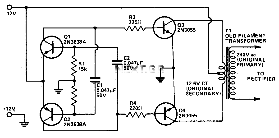
Basic inverter circuit consists of a DC source connected to the primary winding of a transformer through the center tap and a switching mechanism is provided to generate alternate currents in the secondary winding of the transformer. In earlier days they used mechanical switches but now we use electronic switches by using transistors.
Thus we need to connect two transistors and bias them in such a way that only one is active at a time whereas other one remains inactive. You can play with biasing resistors to enhance the efficiency of the inverter. Suppose you have a 5A/12-0-12 Volt transformer. If you will feed any oscillating signal of 12 volt signal at its primary winding the output will be 220V.
You can use any oscillator circuit using transistors, IC 555 or any digital ICs. The output watt depends on the current supplied at primary(input) of the transformer. To feed high current 5A at input you must need a power driver circuit using any transistor like 3055 or MOSFET based. In that case you can generate a 220V, <=60 Watt ( apx depending on the efficiency of transformer) output. Please see the attachment for more detail. 🔗 External reference
Related Circuits
This inverter utilizes standard components instead of specialized parts like the toroidal transformer commonly found in many inverters. The design maintains a low cost by employing inexpensive, readily available components. Essentially, it functions as a power amplifier driven by...
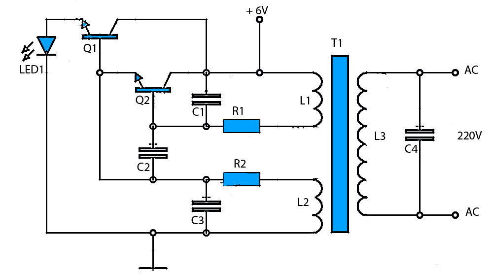
6V to 220V Inverter Schematic. Starting from a 6-Volt input on the DC current to produce a 220-Volt AC output. The inverter circuit converts a low voltage DC input, specifically 6 volts, into a high voltage AC output of 220...
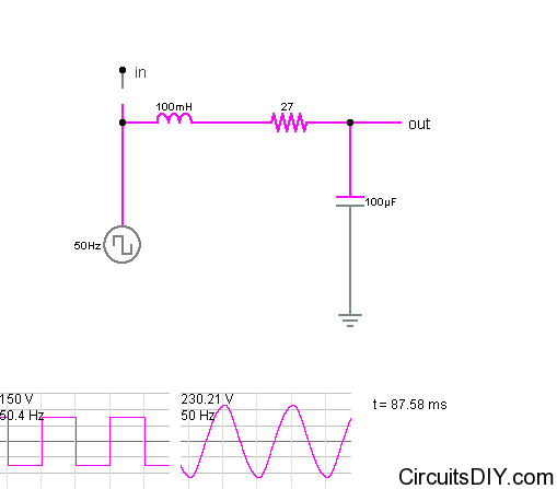
It is relatively easy to find square wave inverter circuits online. However, to operate most loads such as fans and televisions, a sine wave inverter is required. Constructing a sine wave or near-sine wave inverter is more complex and...
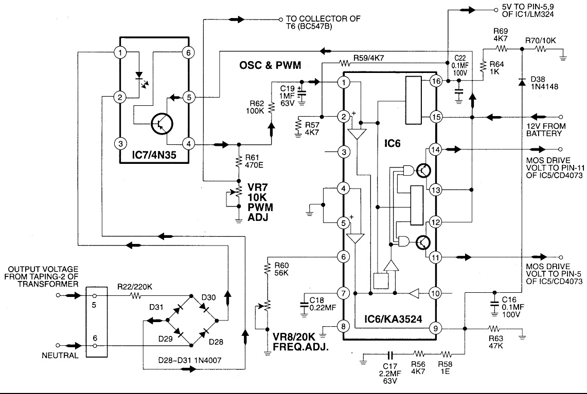
Circuit No. 1 (Oscillator Circuit and Feedback Circuit) Circuit No. 2 (MOS Driver Circuit) Final Product: - Operation of Circuit No. 1 (Oscillator Circuit and Feedback Circuit) This inverter utilizes Pulse Width Modulation (PWM) technology. The working principle of...

This type is commonly used by home users for their PCs. An Uninterruptible Power Supply (UPS) is designed to provide filtration against power failures and manage power flow, while also being efficient, compact, and cost-effective. This type is frequently...
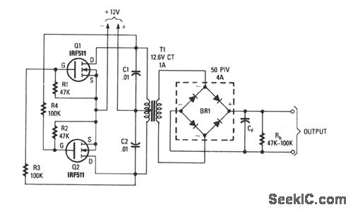
This inverter is capable of delivering high-voltage AC or DC, utilizing a rectifier and filter, with outputs reaching several hundred volts. The transformer T1 features a power rating of 12.6 to 440 V, with the primary and secondary windings...