
Inverters form three-phase VCO

The Voltage-Controlled Oscillator (VCO) described utilizes a configuration of unbuffered U-type inverters arranged in a ring oscillator format. This design is inspired by classic application notes from Texas Instruments, which highlight the effective use of these inverters in generating oscillatory signals.
In this circuit, an odd number of inverters is essential, as it ensures that the feedback loop introduces a negative or inverting feedback mechanism. This configuration is crucial for maintaining the oscillation since it allows the signal to propagate through the loop, creating a continuous oscillatory output. The generated waveforms are characterized as relatively squarish, which is typical for ring oscillator designs due to the sharp transitions between high and low states.
The operational principle of the ring oscillator hinges on the concept of loop gain. For the circuit to oscillate, the loop gain must exceed unity. This condition ensures that the feedback signal is strong enough to sustain oscillations. Moreover, the feedback mechanism establishes an initial bias equilibrium at the transition voltage of the inverter gates, allowing for stable operation.
The implementation of this VCO can vary based on the number of inverters used, as any odd number will suffice. Careful consideration must be given to the specific characteristics of the inverters employed, including their switching speeds and propagation delays, as these parameters will influence the frequency and stability of the oscillation.
Overall, the described circuit serves as a foundational design for various applications requiring oscillatory signals, including clock generation, signal modulation, and frequency synthesis. The simplicity of the configuration, coupled with its effectiveness, makes it a valuable reference for engineers and designers working in the field of electronics.The inspiration for the VCO in Figure 1 came from Texas Instruments application notes of years ago, detailing the use of unbuffered U-type inverters for use in ring oscillators. The application notes circuit consists of only the inverters. The circuit generates relatively squarish waveforms. Any ring oscillators operation depends on the fact that an odd number of inversions exists around the loop.
Any odd number of inverters would work.The feedback is inverting, or negative. The feedback creates an initial bias equilibrium at the transition voltage for the gates. Loop gain greater than unity is a necessary condition for oscillation. Unbuff
🔗 External referenceRelated Circuits
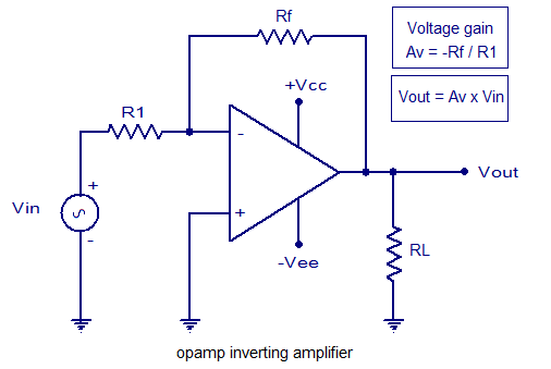
An inverting amplifier utilizing an operational amplifier (op-amp). This includes equations for voltage gain and output voltage, as well as input and output waveforms, and a practical inverting amplifier circuit using the 741 IC. An inverting amplifier is a fundamental...
An increasing number of appliances draw a very small current from the power supply. If designing a mains-powered device, one can generally choose between a linear and a switch-mode power supply. However, when the appliance's total power consumption is...
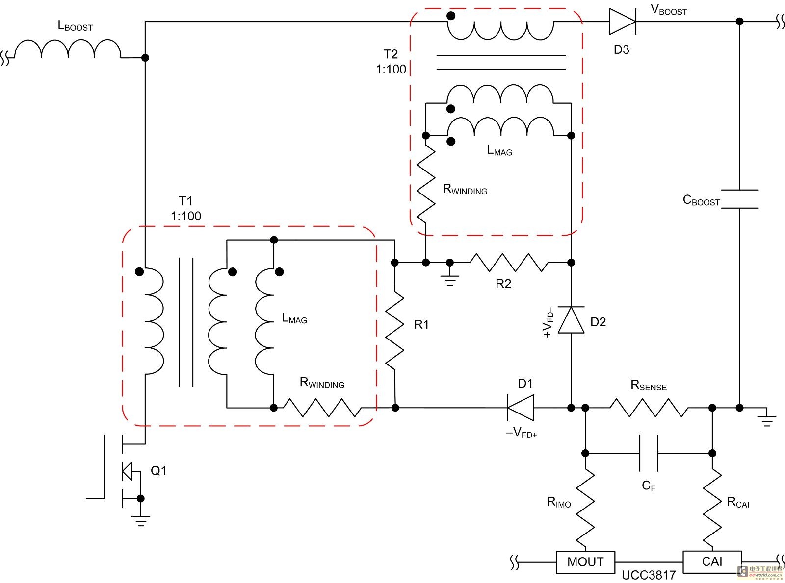
Mode control of the average current (CMC) is necessary to regulate the overall waveform of electric current during the rebuilding cycle. This text recommends selecting specific parameters related to the voltage transformer and outlines steps for designing a circuit...
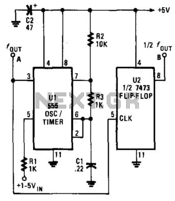
The Voltage-Controlled Oscillator (VCO) has an output frequency that ranges from 1500 Hz at Vcontrol = 1 V to 300 Hz at Vcontrol = 5 V. The resistive component R1 or the capacitive component C1 can be adjusted to...
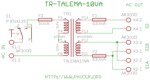
All DAC boards include a power supply section. It is sufficient to connect only a power transformer. This board is designed for a toroidal 10VA transformer manufactured by Talema, which features pins for PCB connection and exhibits minimal electromagnetic...
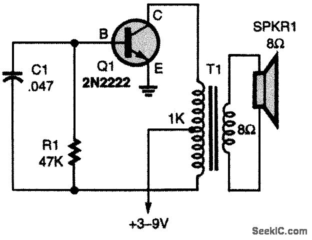
The oscillator circuit employs a center-tapped transistor output transformer that functions as a load for the collector of Q1, provides a feedback signal to the base, and acts as the output winding to drive the speaker. Resistor R1 supplies...