
Simple 555 Vco

The described Voltage-Controlled Oscillator (VCO) operates by varying its output frequency based on the control voltage applied. The specified frequency range indicates that at a lower control voltage of 1 V, the output frequency peaks at 1500 Hz, while at a higher control voltage of 5 V, the frequency decreases to 300 Hz. This characteristic allows for fine-tuning of the oscillator's frequency by adjusting either the resistor R1 or the capacitor C1, which are integral components in determining the time constant of the oscillator circuit.
The component U2 plays a crucial role in this configuration by providing a symmetrical square-wave output. This output is significant as it is generated at half the frequency of the main timer frequency, effectively allowing for dual frequency operation from a single circuit configuration. The symmetrical nature of the square wave ensures that the output has equal high and low durations, which is essential for many digital applications where timing and signal integrity are critical.
In designing the VCO circuit, careful selection of R1 and C1 is necessary to achieve the desired frequency range and stability. The circuit may also include additional components such as diodes for protection against voltage spikes, or op-amps for signal conditioning, depending on the intended application. The overall layout should ensure minimal interference and optimal performance, with considerations for power supply decoupling to maintain signal integrity.
This VCO configuration is useful in various applications, including modulation schemes in communication systems, signal generation for testing and measurement equipment, and as a timing source in digital circuits. The VCO has an output frequency that ranges from 1500Hz at V;,= 1 V to 300Hz at V;,=5 V. R1 or C1 can be varied to change th is range. U2 provides a symmetrical square-wave output of half the timer frequency.
Related Circuits
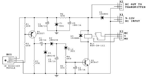
This door minder electronic project is based on a 555 timer circuit and utilizes an infrared (IR) beam to monitor doorways, passageways, or any other designated area. When the IR beam is interrupted, a relay is activated, which can...
This alarm circuit is based on two 555 timers. The alarm will sound your car horn if anyone opens the car door while the circuit is armed. The timers will allow you to leave the car without sounding the...
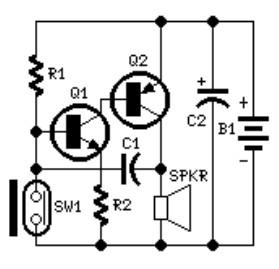
The system involves positioning a small magnet near the stalk switch SW1, which is connected to the hand or garments of the individual carrying the bag via a tiny cable. Due to the compact nature of the circuit, it...
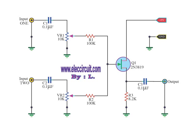
This circuit is a simple mixer circuit that can mix two signal channels into one output channel. It utilizes a codec circuit to convert stereo audio to mono audio. The main component in this circuit is a FET, specifically...
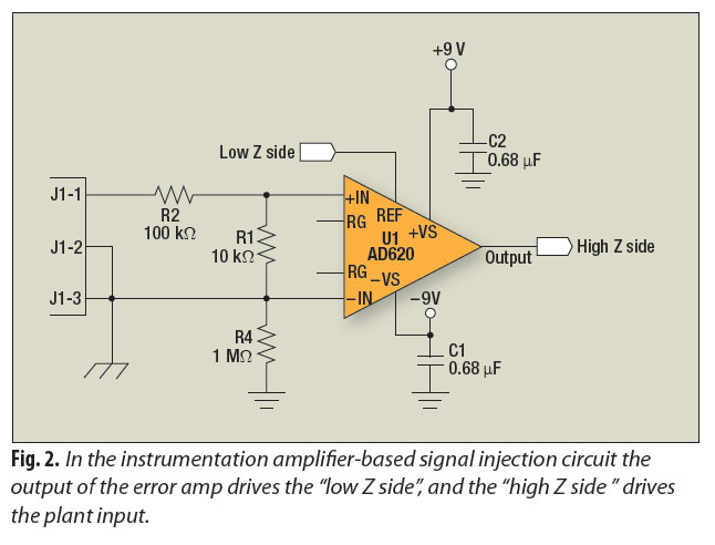
A signal-injection circuit for control-loop analysis is flat from DC to 200 kHz, isolated from chassis ground, and easily constructed with a readily available instrumentation amplifier. The signal-injection circuit is designed to facilitate control-loop analysis by providing a stable and...
Adding this combination audio circuit, as illustrated in figure 14-38, to the automatic rhythm generator of electronic musical instruments fulfills the players' demand for incorporating drum and cymbal audio, enhancing the overall performance effect. The diagram indicates that the...