
iphone battery pack

The design of the battery pack circuit for Apple devices involves several critical components and configurations to ensure proper functionality. The circuit primarily consists of a USB socket, resistors, capacitors, a voltage regulator, and the alkaline batteries. The USB socket is the interface for connecting the charger to the Apple device, and it must be soldered correctly to maintain the required pin configuration.
In terms of power supply, standard alkaline batteries can be used to create a battery pack that outputs a voltage suitable for charging Apple devices. The circuit requires a stable output of 5V from the first pin of the USB socket, which is necessary for the device's charging process. The second and third pins must be set to 2V, which may serve specific signaling purposes for the device. The fourth pin is designated as ground, completing the circuit.
When assembling the circuit, attention must be given to the orientation of the USB socket, ensuring that the hollow section is at the bottom and the pins are at the top. This orientation is crucial for the proper alignment of connections. The choice of PCB board can affect the soldering process, as different boards may have varying copper insertions that dictate where components can be attached.
For the power source, any battery rated above 6 volts can be utilized, providing flexibility in battery selection. However, care must be taken to ensure that the voltage does not exceed the limits that the Apple device can handle. Once the battery pack is assembled, the user can connect a USB charger cord to the battery pack and subsequently to the Apple device, enabling charging functionality.
This overview serves as a foundational guide for the construction of a battery pack circuit tailored for Apple devices, emphasizing the importance of proper soldering techniques and component configuration to achieve a reliable power supply.How to create a Battery pack for your Apple device that is powered by normal Alkaline batteries. This will be a general overview of building the circuit for the battery pack and the detailed instructions for the case will be given in part 2 of this post. NOTE: When soldering the USB socket, face the open part to the right with the connector pins facing left, as in the schematic.
Inside the socket, you will see that there are "2 halves", a hollow half and a half with pins. Make sure that the hollow half is on the bottom and the pins are on the top. This circuit is necessary for the charger to be accepted by the Apple device. Basically, the USB socket must have exactly 5V on the first pin, 2V on the second and third pins, and ground on the fourth pin. I cannot give step-by-step instructions for soldering in each and every resistor, wire, capacitor, regulator, ect.
because depending on the type of PCB board you buy, the pre-made copper insertions on the back of the board are different. Any type of battery above 6 volts will work for this circuit. To use this circuit, just plug in your USB charger cord and plug it into your Apple device. 🔗 External reference
Related Circuits

This is an automatic battery charger circuit that utilizes the LM324 integrated circuit, which enhances efficiency. It is capable of charging both 12V and 6V batteries, with filtration managed by switch S1. The circuit is designed to stop charging...
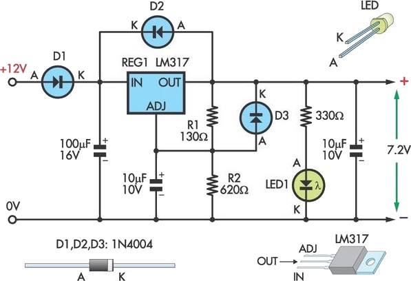
This circuit allows an external 12V SLA battery to power a camcorder that typically operates with a built-in 7.2V battery. Replacement batteries for older camcorder models can be challenging or costly to find. Essentially, the circuit utilizes a standard...
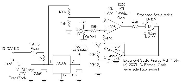
This circuit is designed to measure the voltage of a 12V nominal lead-acid rechargeable battery system. While it was specifically created for solar-powered systems, it is versatile enough for use in automotive or other 12V applications. Lead-acid batteries typically...
This article describes a circuit for a simple single-cell lithium-ion battery charger utilizing the LP2391 regulator IC. The circuit presented is designed for charging a single-cell lithium-ion battery efficiently. The LP2391 is a linear voltage regulator that provides a constant...

The battery should charge up to 14 volts. A reading of 10.7 volts indicates that one cell is shorted. A good way to diagnose this further is to look at the water level in the cells. The shorted cell...
This is a battery tester circuit. This circuit is used to indicate whether the level of a battery voltage is normal, under-voltage, or over-voltage. The battery tester circuit is designed to assess the voltage level of a battery and provide...