
IR 4 channels remote control with PIC12F629

Setup instructions to program the controller and record the desired keys.
Step 1 - Remove power and install a jumper wire from the input (pin 4) to ground.
Step 2 - Turn on 5-volt power to the circuit and the activity LED will flash 3 times and remain on.
Step 3 - Remove the jumper from pin 4 and the activity LED should flash three more times and remain on.
Step 4 - Press the desired keys in sequence to record the keys. The first key must be pressed twice to allow the program to establish the timing on the first press. To program keys 1 to 5, press 1, 1, 2, 3, 4, 5. At each keypress, the indicator should flash 3 times and remain on.
Step 5 - At this point, the indicator light should be out and you can test each key to verify it toggles the correct output. The data is stored in non-volatile EEPROM, so when the circuit is rebooted without the jumper, it should be ready to use with the existing programmed data. For test purposes, it may be beneficial to install LEDs and resistors on the 4 outputs to verify correct operation.
The circuit employs an IR receiver module, which is responsible for receiving infrared signals from a remote control. The PIC12F629 microcontroller decodes these signals, allowing the user to control up to four outputs through the pressing of designated keys on the remote. The fifth key serves as a master clear function, turning off all outputs.
The microcontroller is programmed to recognize specific pulse patterns corresponding to the keys pressed on the remote. The programming process involves temporarily connecting an input pin to ground to enter programming mode, during which the user can define the signals corresponding to each key. The use of non-volatile EEPROM ensures that programmed data persists even when power is removed.
The circuit's power supply can range from 2 to 5 volts DC, making it versatile for various applications. The choice of a 3.6-volt lithium battery is practical, given its common use in portable devices.
For output verification, the addition of LEDs and appropriate resistors on the output pins allows for visual confirmation of the toggling function. This setup aids in debugging and ensures that the circuit operates as intended.The circuit above illustrates using the IR receiver module along with a PIC12F629 microcontroller to decode 5 individual IR remote control keys so the circuit will only toggle one of the 4 outputs when a particular key is pressed. The 5th key is assigned to the master clear function that toggles off the 4 outputs. Works with most hand held IR remote controls that send a single data stream. However, some remotes send multiple groups of data and only the first set of 40 bits or less will be recognized.
This may result in the circuit responding to more than one key, or a single key may control more than one toggle switch. In most cases this problem can be resolved by selecting an alternate function on the remote such as (TV, DVD, SAT, AUX, Etc.). Circuit power supply is not critical and should operate on any voltage from 2 to 5 volts DC. I use a single 3.6 volt recharageable lithium battery such as found in cell phones. Setup instructions to program the controller and record the desired keys. Step 1 - Remove power and install a jumper wire from the input (pin 4) to ground. Step 2 - Turn on 5 volt power to the circuit and the activity LED will flash 3 times and remain on.
Step 3 - Remove the jumper from pin 4 and the activity LED should flash three more times and remain on. Step 4 - Press the desired keys in sequence to record the keys. The first key must be pressed twice to allow the program to establish the timing on the first press.
So to program keys 1 to 5 you would press 1,1,2,3,4,5. At each keypress, the indicator should flash 3 times and remain on. Step 5 - At this point, the indicator light should be out and you can test each key to verify it toggles the correct output. The data is stored in no-volitile EEPROM so when the circuit is re-booted without the jumper it should be ready to use with the existing programed data.
For test purposes, you may want to install LEDs and resistors on the 4 outputs to verify correct operation. ----------------------- PIC12F629 HEX File ---------------------- :10000000000000008A0107309900850183169F01D6 :10001000C83085008312A501A901A701A201A70A82 :10002000FA30AA00453084001A30A000A30123084A :1000300083169B001C141A0883128000840AA30AEA :10004000A00B17281821851956285D308400193017 :10005000A00080018403A00B2928851D2D281821CC :1000600085193028851D322885193428B401851D4D :100070003728A50185194C282508031034020318D8 :1000800044282508B4003728250803102A02031C39 :100090004B282508AA004328A50A0821A51B51289A :1000A0003A282A08B407340CDE00A915C001C101A2 :1000B000C201C301C401A9191821A91D05112210EB :1000C0008519602805154030A91D7528A70DA718AA :1000D000453027194A30A7194F30271A5430A71A2C :1000E0005930271F7528A701A70AB40184000830DA :1000F000A600851D792885197B28A501851D7E28E8 :10010000851D882808210311A50A03199A2880282B :100110002830340603197D28B40A0310800D5E08C8 :100120002502031800140310A60B9928840A08302E :10013000A6007D280311A919E228B001A10105300C :10014000A0000530B0074030B10022103108AE00E9 :100150003007AF00D720B10AA00BA6282108B7208E :100160000630A1071E302106031D9F28E228221811 :10017000080082078518BE288514BF28851008004E :10018000051AC4280516C52805120800851ACA28AC :100190008516CB28851208000518D0280514D1280B :1001A00005100800851205128510051008002E089C :1001B00084000008B2002F08840000083206031DE6 :1001C000221408000D210D21A91D5628A71E56280E :1001D0001930A000A300A30A5E3084000008831633 :1001E0009A008312200883169B001C1555309D0031 :1001F000AA309D009C1483128C1FFC288C131C11A8 :100200008403A003A30BEE28A701A70AA90156287F :100210000F30A300A30B0A290800FF30A300132905 :10022000A30B13290800FF30A000A00B15291029EB :1002300005110D2105150D2105110D2105150D21A6 :0A02400005110D2105150D21080020 :02400E00043F6D :00000001FF
🔗 External reference
Related Circuits
This page outlines the hardware and software design of a printer power switch that is controlled via USB from a Linksys NSLU2, also referred to as Slug. Although primarily designed for printer control, the unit can manage any device...
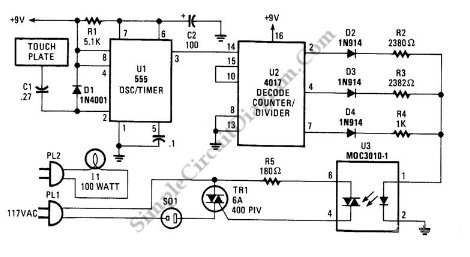
This is a three-mode lamp dimmer circuit with touch control. This circuit can be used to control a lamp in three operation modes: dim, off, and bright. It utilizes a NE555 timer. The three-mode lamp dimmer circuit designed with touch...
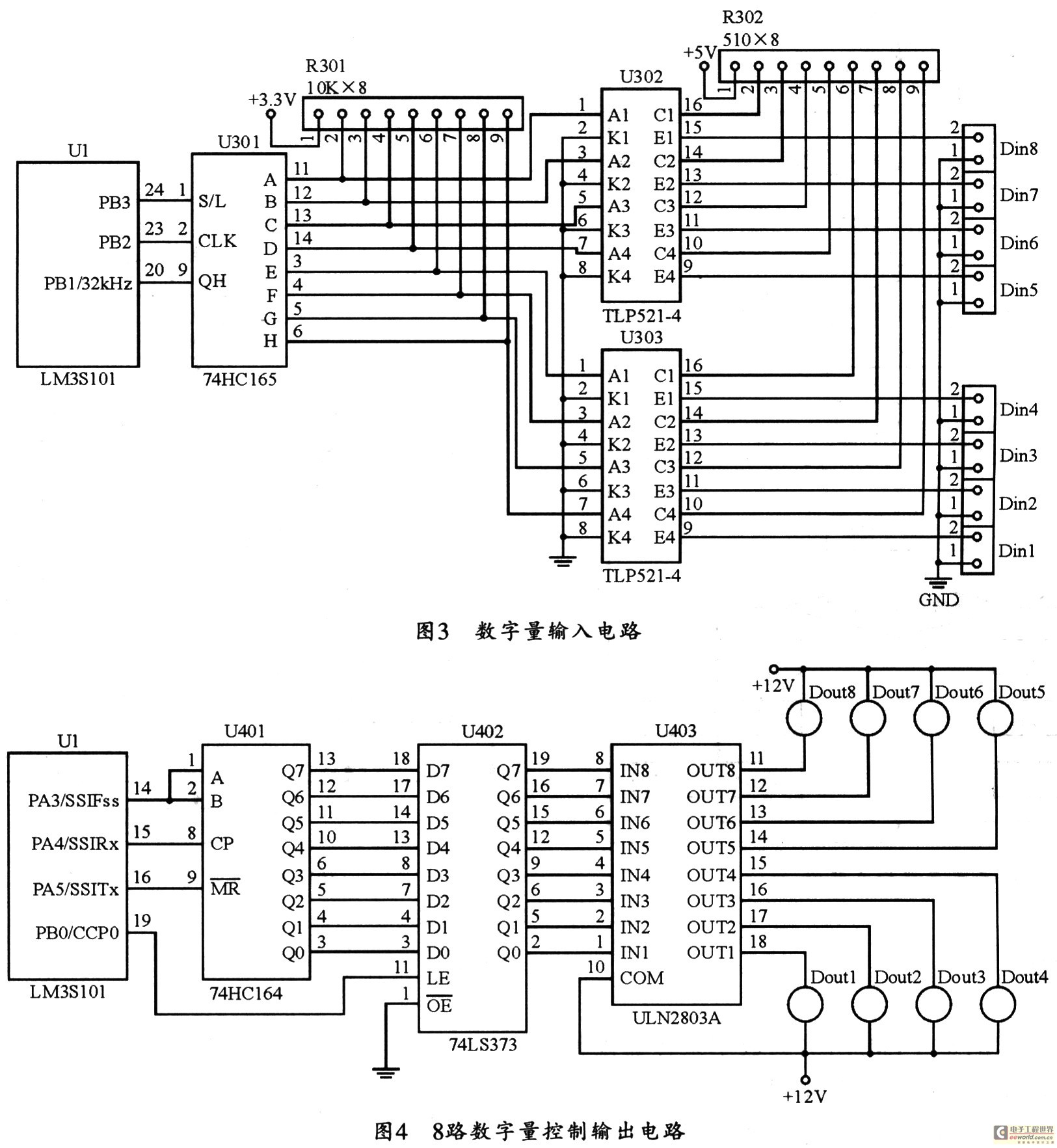
The figure utilizes a controller as the primary equipment for gathering and controlling digital data within an on-site monitoring system. The stability of on-site control operations is crucial to the overall system performance. Therefore, a simple and stable structure...
Low-cost water pump controller circuit. The sensors used in the circuit can be any two conductive probes, preferably resistant to electrolytic corrosion. For example, a suitably sealed audio jack can be employed as the sensor. The automatic pump controller...

This is a universal remote control that was constructed using 1KB of memory. It operates with televisions utilizing the RC5, RC80, and NEC protocols, which cover the majority of TV models. The remote has an effective range of approximately...
Another JYB type liquid level controller internal circuit is shown. This circuit employs a Schmitt trigger configuration, enhancing the reliability of the action level controller. The JYB type liquid level controller utilizes a Schmitt trigger circuit composed of transistors VT2...