
remote control circuit

The universal remote control is designed to provide compatibility with a wide range of television models, utilizing widely adopted protocols such as RC5, RC80, and NEC. The microcontroller at the heart of the design is programmed to handle infrared (IR) signal generation and reception, enabling it to communicate effectively with various television sets. The effective range of 40 meters ensures that the remote can operate from a significant distance, while the 60-degree angle of effectiveness allows for flexibility in user positioning.
The schematic design phase, executed in ExpressSCH, includes the essential components such as the microcontroller, resistors, capacitors, and LEDs. The microcontroller is powered by a regulated voltage supply, ensuring stable operation. Resistors are strategically placed to limit current to the LEDs and to set appropriate operating conditions for other components. The schematic is carefully laid out to minimize interference and ensure reliable signal transmission.
The 3D modeling in Google SketchUp aids in visualizing the remote's physical design, allowing for ergonomic considerations and user interface layout, such as button placement and display positioning. The transition to ExpressPCB for the printed circuit board (PCB) layout involves arranging components in a manner that facilitates efficient signal flow and minimizes trace lengths, which is crucial for high-frequency applications like IR communication.
The manufacturing process includes the use of photosensitive chemicals for etching the PCB, followed by precise cutting and soldering of components. This method ensures a high-quality finish and reliable connections. The debugging process is critical, as it involves testing the functionality of the remote control, verifying the correctness of the programmed code, and ensuring that all components operate as intended. The use of tools such as a multimeter and digital oscilloscope provides valuable insights into the performance of the circuit, while MPLAB SIM allows for simulation of the microcontroller's operation under various conditions.
Overall, the development of this universal remote control showcases a comprehensive approach to electronic design, integrating schematic design, physical modeling, PCB fabrication, and thorough testing to create a functional and user-friendly device.This is a universal remote control I built. The entire thing was programmed with just 1KBof memory, and works with TV`s using the RC 5, RC 80, and NEC protocols (most TV`s). Its effective range is about 40m, and is effective at angles up to 60 degrees. I began by using ExpressSCH to lay out a schematic of the circuit required to power the micropro cessor and LEDs. I used I then usedGoogleSketchUpto create amocked up3D model of the remotes appearance. Using ExpressPCB, I then arranged the parts in a real world design that would fit the mock up. I calculated all the required values for parts, such as resistance for the resistors, and current for the LEDs, thenorderedthem from Digikey. com. I then used circuit board coated with photosensitive chemicals to print my circuit onto the board, through a multi-step chemical process.
After cutting the board down to size, I soldered all the parts in. The process of programming and debugging required the largest majority of time. I programmed in MPLAB, and used, a multimeter, digitaloscilloscope, CHRP board (see here ), and MPLAB SIM to debug. 🔗 External reference
Related Circuits
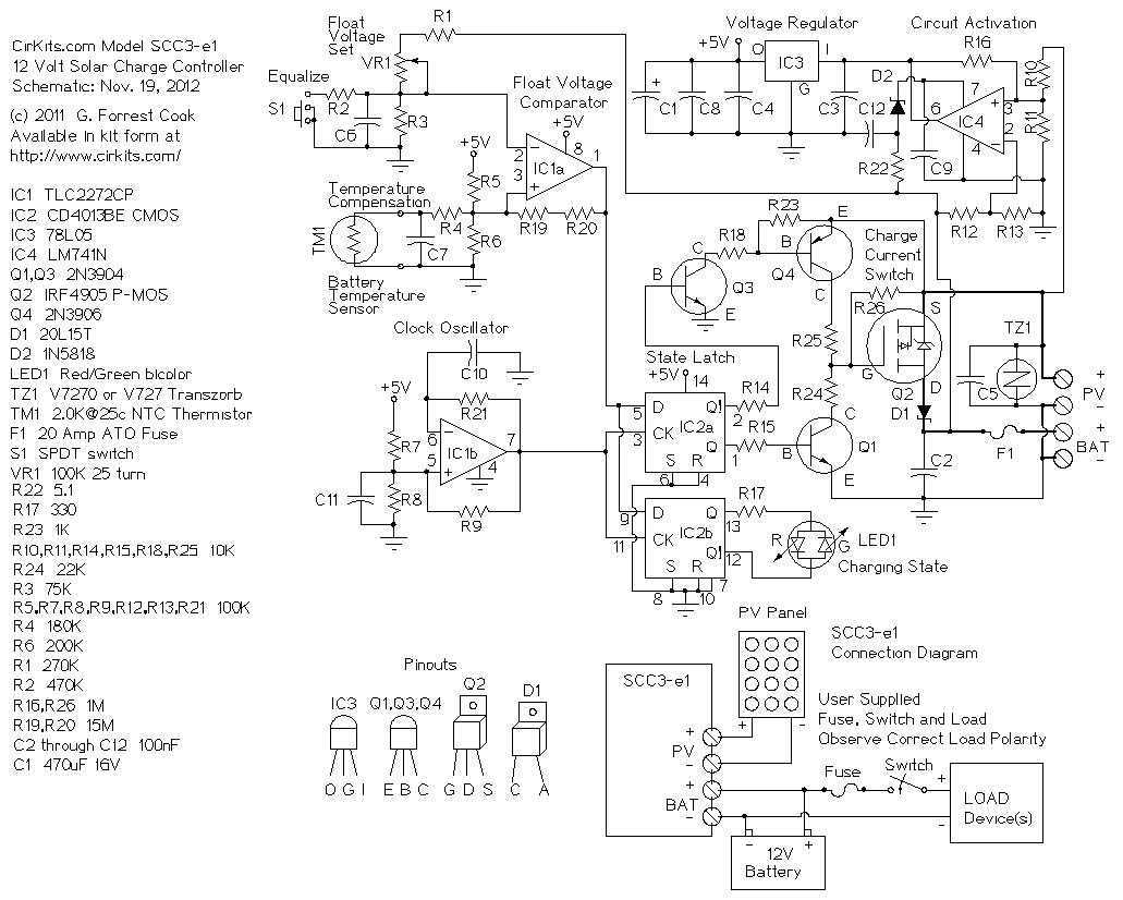
The SCC3 is a solar charge controller. Its function is to regulate the power flowing from a photovoltaic panel into a rechargeable battery. It features easy setup with one potentiometer for the float voltage adjustment, an equalize function for...
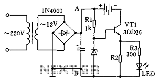
A practical single-tube constant current charger is illustrated, utilizing a transistor (VT1) that plays a crucial role in maintaining a constant current. The current value is determined by the voltage regulator and resistor R2. The general output voltage is...
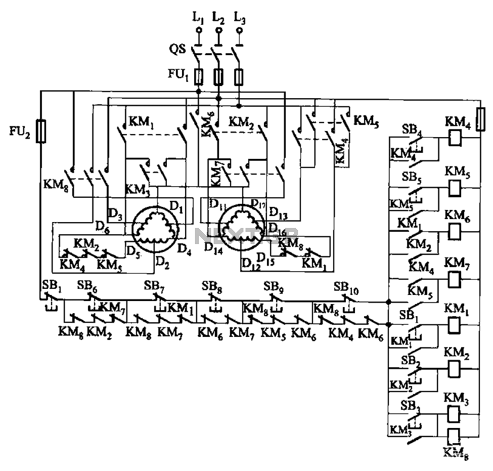
The circuit depicted in Figure 3-120 allows for the control of a motor with a capacity of less than the rated current of 5A by using an intermediate relay instead of a contactor. This circuit enables four forward running...
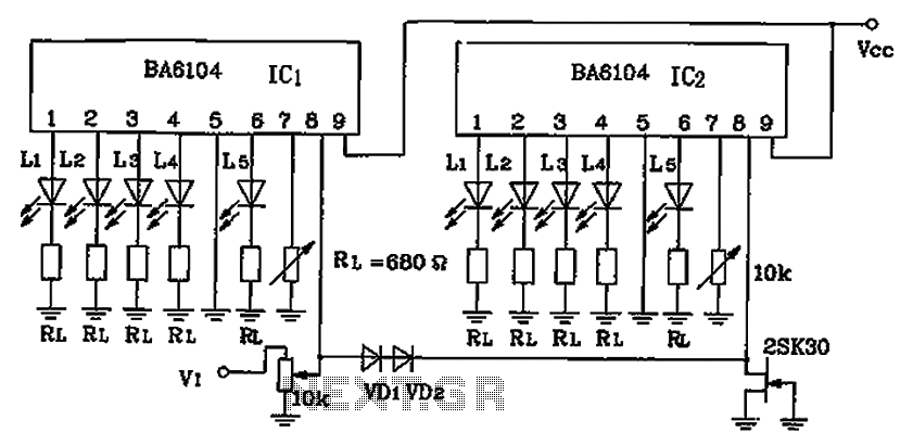
BA6104 is a five-digit LED level meter that functions as an LED display driver integrated circuit (IC). The configuration of the circuit is illustrated in the accompanying figure. The circuit utilizes a 10 by two-dot LED level display. The...
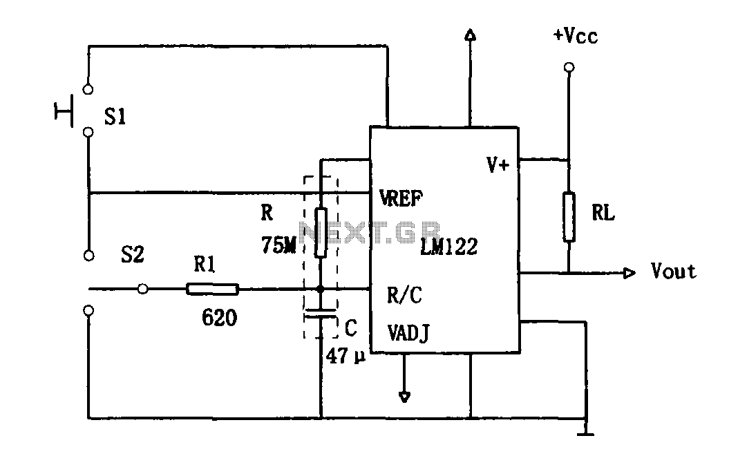
As illustrated in Figure 1, the circuit utilizes an LM122 timer. The circuit's start, reset, and stop functions are managed through switching operations. Switch S1 initiates the timing sequence when the timer is activated; thereafter, this switch has no...
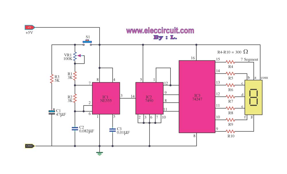
This digital dice circuit is designed to display numbers effectively. When the spin switch is turned off, it converts the input into a binary format using a diode matrix composed of diodes D1 to D9 (1N4148 or 1N914). This...