
Low Cost Water Pump Controller Circuit
The low-cost water pump controller circuit effectively automates the operation of water pumps, enhancing efficiency and convenience. The core of the circuit relies on two conductive probes that serve as water level sensors. These probes detect the presence or absence of water, triggering the pump's operation when the water level falls below a predetermined threshold.
The circuit utilizes a microcontroller or a simple comparator to interpret the signals from the probes. When the water level is low, the circuit activates the pump, allowing water to be drawn from the reservoir. The inclusion of a 7-segment display provides clear visual feedback, indicating the current water level in the tank. The display can show three states: 'L' for low, 'H' for half, and 'F' for full, allowing users to monitor the water levels easily.
To prevent overfilling, a buzzer is integrated into the circuit, which sounds an alarm when the water level reaches a critical point. This feature serves as an important safety measure, alerting users to potential overflow issues.
The design of this circuit is straightforward, employing readily available components. The use of a sealed audio jack as a sensor is particularly advantageous due to its resistance to corrosion, ensuring longevity and reliability in various environments. The overall simplicity of the circuit makes it accessible for individuals with varying levels of electronics experience, facilitating easy assembly and implementation in residential or agricultural applications.Low Cost Water Pump Controller Circuit. The sensors applied to the circuit could be any two conducting probes, preferably resistant to electrolytic corrosion. For example, in the easiest case, a appropriately sealed audio jack could be utilized to operate as the sensor.
Here the circuit diagram of low cost water pump controller. The automatic pum p controller minimizes the need for any manual switching of water pumps installed for the functionality of pumping water from a reservoir to an overhead tank. It instantly switches on the pump once the water level within the tank falls below a. Here the water-level indicator which use a 7-segment display, to show the water level (low, half and full) in the tank.
Moreover, a buzzer is utilized to warn you of water overflowing from the tank. The circuit shows the water level by displaying L, H and F for low, half and full, respectively. The circuit. Here the notebook anti theft protector circuit to secure your important netbook / notebook from stealing. Basically, this is a mini security alarm generator. Fixed inside the notebook case, it will definitely sound a noisy alarm when a person attempts to grab the notebook.
This very sensitive circuit utilizes a homemade tilt switch to turn. This is the circuit diagram of automatic light controller which use 78xx voltage regulator IC series. The voltage regulator ICs deliver a constant output voltage, as against a extensively fluctuating input supply, when the common terminal is grounded.
Any voltage about zero volt (ground) interconnected within the common terminal is added to the output voltage. . This is a low-cost and simple intercom circuit design. Some intercom circuits is build by applying integrated circuits. The circuit described right here utilizes 3 certainly transistors which easy to find on the electronic store.
Even a newbie can assemble it on a piece of veroboard without difficulty. The circuit consists of a 3-stage resistor-capacitor. Above circuit diagram is a easy, simple and cheap switching voltage regulator which has capability to deliver adjustable voltage output range of 1. 8V to 32V and static electric current of 3A. This regulator use adjustable regulator IC of LM317HV and a power PNP transistor of 2N3792. The LM317HV is adjustable 3-terminal positive voltage regulators capable. 🔗 External reference
Related Circuits
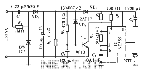
The circuit utilizes a 555 integrated circuit (IC). When an incoming call is received, 220 V AC is stepped down through resistor R1, followed by rectification using diode VD1. A voltage regulator (DW) is employed, and capacitor C2 is...
The simplest of all motor controllers (besides a straight on/off switch) is the contactor controller. Aaron designed this contactor controller for use in his electric scooter project. It is based around three 12V relays, two 12V batteries, two switches...
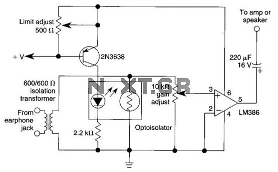
An optoisolator is utilized as an attenuator in this circuit. When the LM386 draws more current from audio signals, the 2N3638 activates, which biases the optoisolator on, thereby reducing the volume. The circuit employs an optoisolator to achieve signal attenuation,...

This is a circuit design for an FSK demodulator, which is an electronic device that converts an FSK signal into a serial digital signal. FSK modulation is used to transmit digital serial data, and demodulation is necessary to retrieve...
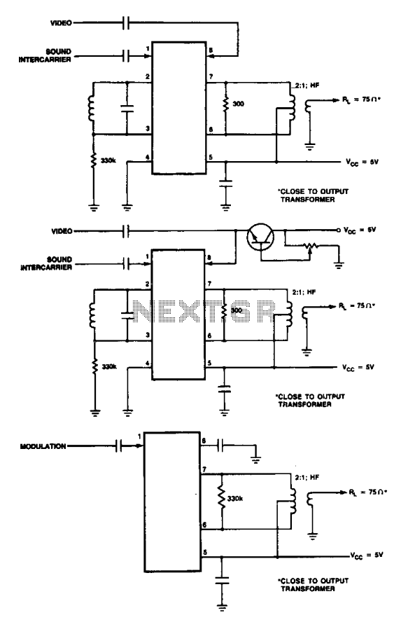
These are modulator circuits designed for the modulation of video signals on a VHF/UHF carrier. The circuits require a 5 V power supply and a few external components for negative modulation mode. For positive modulation, an external clamp circuit...
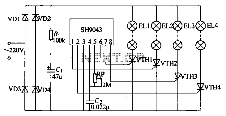
This example demonstrates a robust design featuring novelty lights that flash in a specific sequence, utilizing a 1-3-2-4 vault chase mode. The circuit includes diodes VD1 to VD4, which form a bridge rectifier, converting AC voltage to a full-wave...
Warning: include(partials/cookie-banner.php): Failed to open stream: Permission denied in /var/www/html/nextgr/view-circuit.php on line 713
Warning: include(): Failed opening 'partials/cookie-banner.php' for inclusion (include_path='.:/usr/share/php') in /var/www/html/nextgr/view-circuit.php on line 713