
Ir Detector

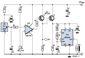
The circuit operates by detecting infrared (IR) light pulses emitted from remote controls or other IR sources. The primary component, Q1, is an IR photodetector that converts incoming IR light into an electrical signal. The output of Q1 is fed into operational amplifier U1A, configured as a voltage follower to ensure that the signal maintains its integrity without being loaded down by subsequent stages.
The differentiating network formed by capacitor C1 and resistor R2 serves to convert the continuous signal from the photodetector into sharp pulses, enhancing the detection of rapid changes in the IR light intensity. The output of this differentiating network is then amplified by operational amplifier U1B, which increases the amplitude of the signal for further processing.
Capacitor C2 is charged by the amplified pulses, and its voltage level is monitored by voltage follower U1C. This configuration allows U1C to provide a stable output that reflects the charge level of C2. The final stage of the circuit involves comparator U1D, which compares the sampled voltage against a reference level. When the voltage from C2 exceeds the reference, U1D activates LED1, indicating the presence of IR light pulses. The LED remains illuminated for a duration of two seconds, providing a clear visual indication of IR signal detection.
This circuit can be effectively used in various applications, including troubleshooting remote controls, testing IR-based alarm systems, and verifying the functionality of other IR-emitting devices. The design ensures reliable operation and clear feedback through the LED indicator, making it a practical tool for electronics testing and diagnostics. Useful for checking TV remote controls, IR-based alarm systems, and IR sources, this circuit causes LED1 to turn on for two sec onds in the presence of IR light pulses. UlA acts as a voltage follower for detector Ql. CI and R2 form a differentiating network and U1B acts as an amplifier for the pulses, which charges C2. Voltage follower U1C samples the voltage on C2 and drives comparator U1D, which switches LED1 on or off.
Related Circuits
The circuit diagram of the Lie Detector is illustrated above. It consists of three transistors (TR1 to TR3), a capacitor (C1), two lights or LEDs (L1 & L2), five resistors (R1 to R5), and a variable resistor (VR1). This...
The overhead detector (fire alarm) circuit utilizes a precision integrated temperature sensor, the LM35 (IC1), which offers an accurate linear output. The overhead detector circuit is designed to monitor ambient temperature levels for fire detection purposes. The core component of...

Phase Lock Loop (PLL) FM Detector with 565 PLL IC. The circuit diagram and internal structure of the PLL IC 565 are shown in the given figures. The Phase Lock Loop (PLL) FM Detector utilizing the 565 PLL IC is...

This zero-crossing detector employs a dual LM393 comparator and allows for easy control of hysteresis through the reference levels set on the comparator inputs. The illustrated circuit is powered by +10 V power supplies, and the input signal can...

Portable loads such as video cameras, halogen flood lights, electrical irons, hand drills, grinders, and cutters are powered by connecting long 2- or 3-pin cables. Portable electrical loads require reliable power sources for efficient operation in various applications. The devices...
One of the simplest methods of metal detection is through a beat frequency oscillator. The circuit consists of two balanced oscillators: one provides a reference signal, while the other acts as the detector element. The frequency of the reference...