
IR DETECTOR CIRCUIT

The described circuit operates as a basic IR signal detection system. The IR phototransistor Q1 is sensitive to infrared light emitted by remote control devices. When the remote control is activated, it emits a modulated IR signal, which the phototransistor detects. The phototransistor is typically connected in a common emitter configuration, allowing it to convert the received IR light into a small current.
The output current from Q1 is insufficient to drive an LED directly, hence the inclusion of the PNP transistor Q2. When Q1 detects the IR signal, it generates a collector current that flows into the base of Q2. This base current turns Q2 on, allowing a larger current to flow from its collector to emitter, thus powering LED1. The LED lights up as a visual indicator that an IR signal has been successfully received.
Proper biasing of both transistors is essential for the circuit's functionality. Resistors may be used in series with the phototransistor and the base of the PNP transistor to ensure they operate within their specified ranges. Additionally, a current-limiting resistor should be placed in series with LED1 to prevent excessive current from damaging it.
This circuit can be used in various applications, including remote control verification systems, IR signal testing devices, and simple home automation projects, where it is necessary to confirm the operation of remote control devices. The simplicity of the design makes it suitable for educational purposes as well, demonstrating the principles of phototransistor operation and transistor amplification.The circuit uses an IR phototransistor, Q1, to detect a remote control`s IR output signal. A PNP transistor, Q2, then amplifies Q1`s output and lights LED1. That indicates that an infrared signal has been detected by the phototransistor, or in other words, that your remote control works. 🔗 External reference
Related Circuits

This circuit generates sine and square wave signals with frequencies ranging from below 20 Hz to above 20 kHz. The advantage of this circuit diagram is that the output frequency can be adjusted by varying the variable resistor R6. The...
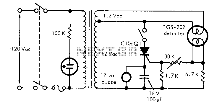
This circuit is capable of detecting smoke and various gases, including carbon monoxide (CO), carbon dioxide (CO2), methane, and coal gas, with a sensitivity of 10 parts per million (ppm). It employs a heated surface semiconductor sensor, which detects...
The schematic diagram has been modified to include a 220µF smoothing capacitor connected between the base of transistor Q1 and ground. This addition effectively mitigated the issue of relay chatter, which involved rapid on/off switching at light levels. The...
This project has not been called a GOLD detector as this name has been left for the more complex detectors that actually discriminate between gold and other metals. There is an enormous difference between detecting gold and ordinary metals...

This is a straightforward 12V power supply circuit diagram. It features a fixed voltage output and is based on the LM7812 voltage regulator integrated circuit. The 12V power supply circuit utilizing the LM7812 voltage regulator is designed to provide a...
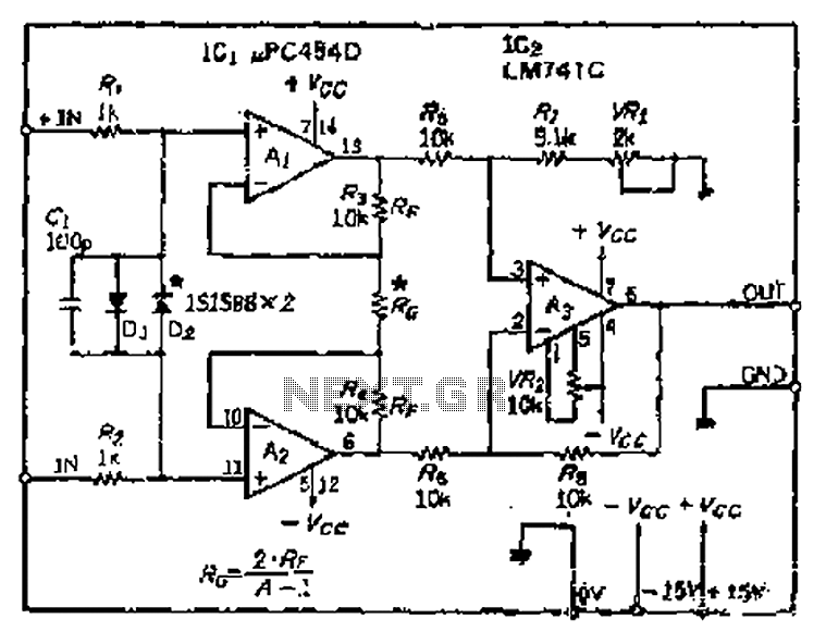
All resistance values are equal, resulting in the Cantonese operational amplifier's gain (A) being equal to 1. However, by selecting smaller resistances, the gain can be adjusted. The circuit can achieve the desired gain through six configurations. Two heavy...