
light dark sensor with relay circuit

The modified circuit design includes essential components such as a transistor (Q1), a relay, a light-dependent resistor (LDR1), a potentiometer (P1), and associated resistors. The smoothing capacitor (C1) plays a critical role in stabilizing the voltage at the base of the transistor, ensuring that it operates smoothly without fluctuations that could cause unwanted relay activation.
When the ambient light level falls below a certain threshold, the LDR1 decreases its resistance, allowing current to flow through the base of Q1. This, in turn, activates the relay, closing the circuit and powering the connected load. The potentiometer (P1) provides flexibility, enabling users to set the sensitivity of the circuit according to their specific requirements.
By swapping the positions of R1 and LDR1, the behavior of the circuit changes, allowing it to operate in a more versatile manner. This adjustment is particularly beneficial for applications where devices need to be turned off automatically during the night, thereby conserving energy.
To enhance the circuit's efficiency for renewable energy applications, it is crucial to consider the selection of components that minimize power consumption. This may involve using a low-power relay or implementing a solid-state relay (SSR) that can operate with minimal current draw. Additionally, optimizing the values of resistors and capacitors in the circuit can further reduce power requirements, making the design more sustainable and suitable for integration with solar panels or other renewable energy sources.We have modified the schematic diagram above with the addition of a 220uF smoothing capacitor between the base of transistor Q1 and ground. Without this capacitor, the relay chatter (relay switching on and off many times per second) was terrible around the switch on/off light level.
By adding the capacitor, relay chatter wascompletely eliminated. According to the designer of this circuit, the relay will be closed only when "NO light falls on LDR1", however, in testing this circuit proved to work very well with the user able to adjust the potentiometer (P1) to automatically close the relay at whatever light level they chose. By swapping the postitions of the 10K resistor (R1) and the LDR (LDR1), the relay will be closed when the LDR is under light rather than under darkness.
Therefore a device can automatically be switched off at nighttime. Since this circuit still contains a relay we need to make some changes* to reduce the amount of power to make it more suitable for renewable energy powered low-current applications. 🔗 External reference
Related Circuits
The diagram illustrates the circuit of a versatile USB power socket that safely converts 12V battery voltage into a stable 5V output. This circuit enables the use of various USB-powered devices. The circuit design consists of several key components to...

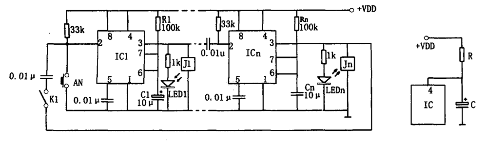
This circuit utilizes three readily available 555 timer integrated circuits (ICs), all functioning as astable multivibrators. The first 555 timer has both an on period and an off period of 1 second. This IC regulates the on/off intervals of...
This acoustic sensor was originally developed for an industrial application (monitoring a siren), but it will also find many domestic applications. The sensor is designed with safety of operation as the top priority, meaning that in the worst-case scenario...
The multi-channel temperature measurement circuit is illustrated in the figure. The core of the test circuit comprises a 555 one-shot delay circuit. When the button is pressed, the output pin of the 555 timer (IC1) goes high due to...
This microphone preamplifier utilizes the low-noise integrated circuit (IC) uA739. It serves as a practical example of designing an effective preamplifier for dynamic microphones. The IC contains two identical integrated preamplifier circuits, with the second preamp functioning in the...
With this circuit we can change the brightness of lamb, with a only key of touch. The key of touch is connected in the circuit, center of which is a special completed IC1, which is the S566B of SIEMENS....