
IR Headset Circuit with headphone Transmitter and Receiver diagram

The infrared headphone circuit operates by converting audio signals into infrared light, which can be transmitted wirelessly to headphones. The circuit consists of two main sections: the transmitter and the receiver.
In the transmitter section, the audio signal from a TV or radio is fed into an audio transformer. This transformer is crucial as it matches the impedance of the audio source to the input of the circuit, ensuring optimal signal transfer. The pre-amplification stage uses the BC547 transistor (T1) to boost the audio signal strength before it is sent to the modulation stage.
The BD140 transistor (T2) functions as a modulator that drives multiple IR LEDs. These LEDs convert the modulated electrical audio signals into infrared light, which can be received by the headphones. The red LED not only indicates that the circuit is powered but also ensures that T2 operates within its optimal range. Powering the transmitter with a 9V battery allows for portability and ease of use, making it suitable for home entertainment systems.
The receiver section utilizes a photo transistor (T3) to detect the incoming infrared signals. The collector of T3 is connected to the base of the BC548 transistor (T4), which amplifies the detected signal. This amplified signal is further processed by the BC549 transistor (T5) to ensure that the audio output is clear and at an appropriate volume level.
Finally, the BC549 transistor (T6) drives the headphones, allowing users to hear the transmitted audio. The receiver is also powered by a 9V battery, ensuring that both the transmitter and receiver operate independently without the need for extensive wiring.
Overall, this IR headphone circuit is an effective solution for private listening, providing a simple and efficient way for users to enjoy audio without disturbing others in their vicinity. The use of common components and straightforward design principles makes it accessible for beginners in electronics.Here is a simple IR headphone circuit that is suitable for listening to TV or radio with out disturbing others. For beginners the IR headset is a better option than FM head sets because they often produce desirable sound quality with out tuning as well as difficult impedance matching that is often done in radio circuits which is difficult for begi
nners. The audio signal is coupled to the base of T1 (BC547) by an audio transformer. The T1 pre amplifies the signal. The transistor T2 (BD 140) drives the IR LED`s which transmit the sound as IR beams. The red LED provides fixed bias for theT2 as well as a power on indication. The transmitter has a 5m range under normal conditions. A 9V battery can be used to power the transmitter. The photo transistor T3 receives the IR signals. The collector of IR is connected to base of T4(BC548) which amplifies the signal together with T5 (BC549)to regain the audio signal transmitted. The transistor T6 drives the headphone to reproduce the sound. The receiver can be powered by using a 9V battery. The audio transformer can be easily obtained from a old transistor radio. It should be connected with the low impedance winding (thicker) to the audio input (TV or radio) side.
🔗 External reference
Related Circuits
The circuit is a DC to DC converter utilizing a standard 12 VAC center-tapped power transformer configured as a blocking oscillator. Although the circuit exhibits low efficiency, it generates a high voltage suitable for low-power applications. The input battery...
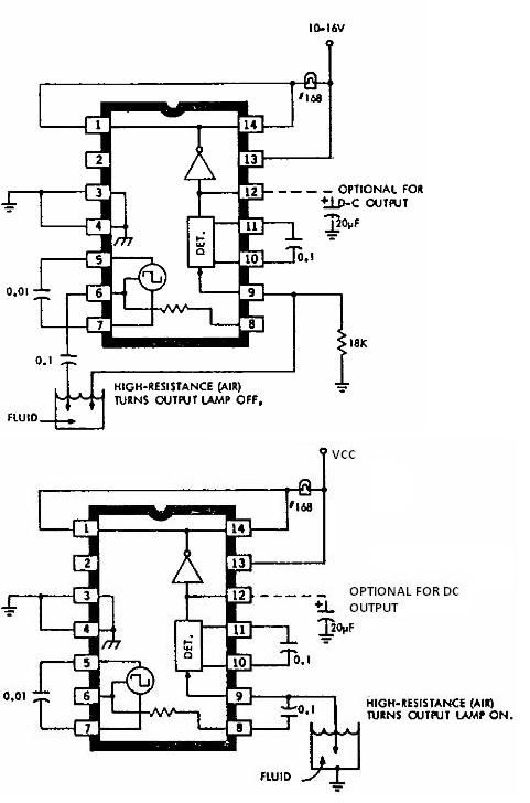
This electronic liquid detector circuit diagram is based on the ULN2429 monolithic bipolar integrated circuit designed for detecting the absence or presence of many different types of liquids. The ULN2429 electronic liquid detector circuit can be used in automotive,...
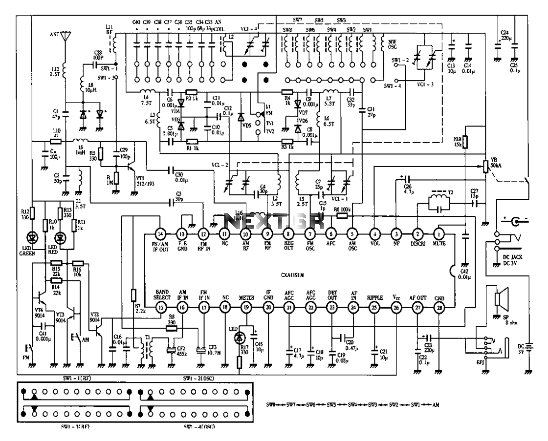
Desheng 1012 is a 12-band radio circuit diagram that covers FM, MW, SW, and TV sound frequencies. The Desheng 1012 radio circuit is designed to receive a wide range of frequencies across multiple bands, including FM (Frequency Modulation), MW...
This circuit is designed for children's entertainment and can be installed on bicycles, battery-powered cars, motorcycles, as well as on models and various games and toys. When switch SW1 is positioned as depicted in the circuit diagram, it generates...
The circuit operates on the principle of detecting smoke produced during a fire. Smoke reduces the amount of light reaching a Light Dependent Resistor (LDR) placed between a light bulb and the LDR. This configuration is known as an...
There are instances when a radio station can be found, and other times when no stations are detectable. The primary issue while tuning appears to be that any movement of the hands or body, such as releasing the tuning...