
ULN2429 liquid detector circuit diagram electronic project

The ULN2429 integrated circuit serves as a versatile solution for liquid detection across various environments. It operates by utilizing a probe that is immersed in the liquid being monitored. The resistance of the probe changes based on whether the probe is submerged in a liquid or exposed to air. This resistance change is compared to a predetermined internal or external reference resistance to determine the liquid's presence or absence.
The circuit can be configured to drive several types of output devices. When a liquid is detected, the output of the ULN2429 can activate an LED to provide a visual indication of the liquid's presence. Alternatively, it can drive an incandescent lamp for more substantial illumination or a loudspeaker for auditory alerts. The design also supports the operation of relays and solenoids, which can be used for automated control systems, such as shutting off a valve or activating a pump.
To ensure the output signal is suitable for these devices, a capacitor must be connected to pin 12 of the ULN2429. This capacitor smooths the output signal, converting the typically generated square wave into a more stable DC signal. This adjustment is critical when interfacing with devices that require a steady voltage supply.
For applications that necessitate higher voltage outputs, the ULN2429A-1 variant is recommended. This version of the integrated circuit retains the same functionality while accommodating devices that operate up to 50 volts, thereby expanding the range of potential applications in industrial settings where higher voltage systems are common.
Overall, the ULN2429 liquid detector circuit is a robust and flexible design suitable for various liquid detection applications, providing reliable performance and ease of integration into existing systems.This electronic liquid detector circuit diagram is based on the ULN2429 monolithic bipolar integrated circuit designed for detecting the absence or presence of many different types of liquids. The ULN2429 electronic liquid detector circuit can be used in automotive, home or industrial applications.
The absence or presence of the liquid is deter mined by comparing the loaded probe resistance (probe immersed in the fluid ) with an internal or external resistance. At the output you can connect a LED, incandescence lamp, loud speaker or even such relays or solenoids, but just I you connect at pin 12 a capacitor, to provide a dc output ( typically the output signal is a square wave ).
If you need to connect at the output a device that need more than 30 volts you can use the ULN2429A-1 which is identical, but support devices with operation up to 50 volts. 🔗 External reference
Related Circuits
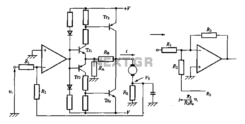
A discrete transistor current control circuit diagram. The discrete transistor current control circuit is designed to regulate the flow of current through a load by utilizing a transistor as the primary control element. This circuit typically consists of a few...
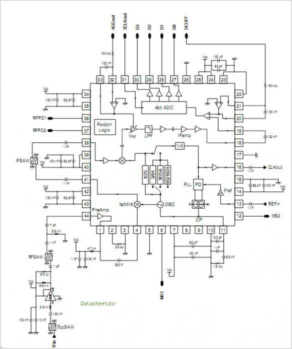
The MAX1896, MAX1973, and MAX8863 are integrated circuits that provide output voltages of 5V at 225mA, 1.8V at 220mA, and 3.3V at 60mA, sourced from a USB port. USB devices typically draw power with a voltage range of 4.5V...
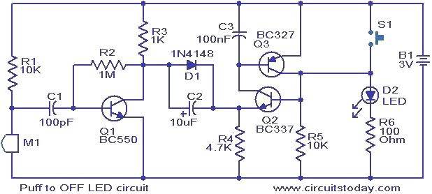
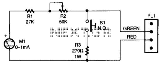
This circuit features an LED that can be turned off with a puff of air. A condenser microphone (M1) detects the puff. When the push button switch S1 is activated, transistors Q2 and Q3, configured as a latching pair,...
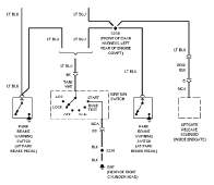
The following circuit illustrates the wiring diagram and electrical circuit troubleshooting for the 1997 Chevrolet Blazer. Features include a 4.3-liter Vortec V-6 engine, an AM-FM stereo radio with CD player, rear-wheel drive managed by a four-speed automatic transmission, air...
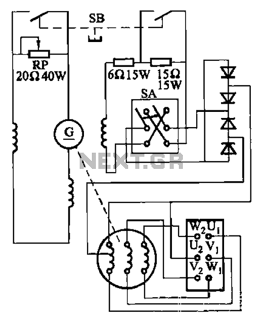
The AX3-300-2 DC arc welding machine circuit is part of the AX, AX1, AX3, and AR series of rotary DC arc welding machines. These machines share a similar structural design, featuring a three-integral unit configuration that combines an inverter...
When the switch SI is pressed, the silicon-controlled rectifier (SCR) is activated, connecting LED1 and resistor R1 across the telephone line. This action causes the line voltage to drop to approximately 20 volts, which maintains the connection to the...