
Desheng 1012 12-band television sound radio circuit diagram

The Desheng 1012 radio circuit is designed to receive a wide range of frequencies across multiple bands, including FM (Frequency Modulation), MW (Medium Wave), SW (Short Wave), and TV sound. This versatility allows the user to access various audio content from different broadcasting services.
The circuit typically includes several key components: a tuner for frequency selection, amplifiers to boost the received signals, and demodulators to convert the modulated signals back into audio. The 12-band feature indicates that the radio can be tuned to 12 distinct frequency ranges, enhancing user experience by providing a broader selection of stations.
The FM band is primarily used for music and entertainment, while the MW band is commonly used for talk radio and news. The SW band allows for long-distance broadcasts, often featuring international stations, and the TV sound band enables reception of audio from television broadcasts.
In the schematic, the tuner section may utilize variable capacitors or inductors to adjust the frequency, while the amplifier sections typically consist of operational amplifiers or transistors configured for audio amplification. The demodulation process may employ a simple envelope detector or more complex methods depending on the design requirements.
Overall, the Desheng 1012 circuit diagram represents a comprehensive design that facilitates multi-band reception, providing users with a versatile radio experience. Proper implementation of the components as per the schematic will ensure optimal performance and sound quality across all selected bands.Desheng 1012 12-band FM, MW, SW, TV sound radio circuit diagram as follows:
Related Circuits
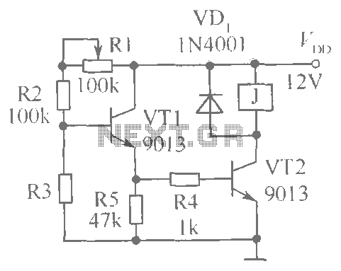
This document presents a brightness control relay circuit. Resistors R1, R2, and R3 create a voltage divider circuit with a light-sensitive resistor. When the light level drops below a specific threshold, the base voltage of VT1 increases, causing VT1...
It is a relatively simple circuit, with which we can have optical and sound clue, when we have telephone ring in the line of telephone. The calls in the line, are changed in pulses of frequency 400 HZ from...
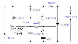
If you wish to take a picture of a fleeting event which generates a sound, you can do it with this sound activated trigger. It does not require any power supply: it feeds on the high voltage available on...
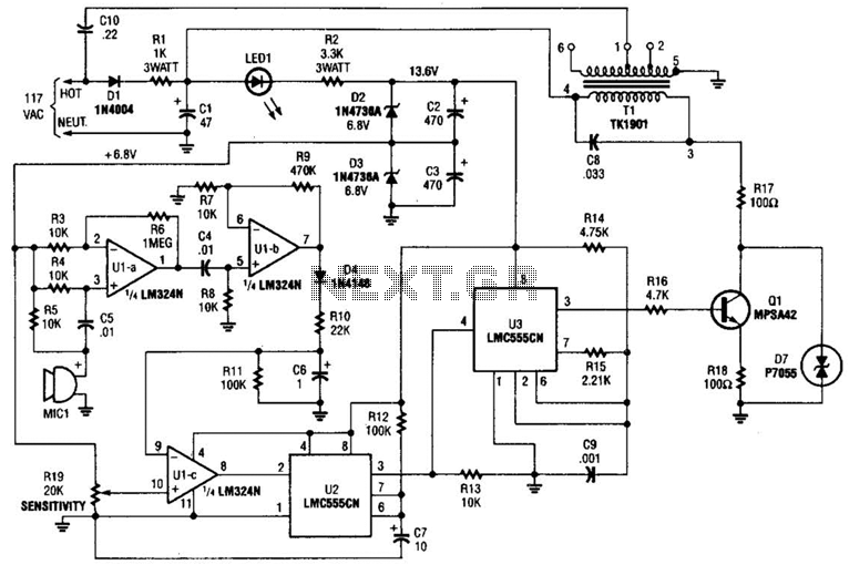
The baby-alert transmitter is constructed using an LM324 quad operational amplifier (U1), two LMC555CM CMOS oscillator/timers (U2 and U3), along with several supporting components. The transmitter activates upon detecting sound at MIC1, emitting a signal. Its operational frequency is...
The thermistor utilized has a resistance of 15k ohms at 25 degrees Celsius and 45k ohms at 0 degrees Celsius. A suitable bead-type thermistor can be sourced from the Maplin catalogue. The inclusion of a 100k potentiometer enables this...
A preamp circuit in a powered subwoofer is producing a static or popping noise, reminiscent of a scratchy or dirty sound. The preamp circuit in question is crucial for amplifying low-level audio signals before they are sent to the power...