
IR On/Off Switch Using Microcontroller

The IR On-Off switch operates by receiving infrared signals from a remote control and using those signals to control an electrical device. The core components include the PIC12F629 microcontroller, which processes the signals received from the TSOP1738 IR receiver. The TSOP1738 is designed to demodulate the infrared signals emitted by standard remote controls, converting them into a format that the microcontroller can interpret.
Upon receiving a signal, the microcontroller executes a simple program that checks for the specific command associated with the memorized key on the remote control. When the designated key is pressed, the microcontroller triggers the relay, which can then switch the connected electrical device ON or OFF. The relay acts as an electromechanical switch, capable of handling higher voltages and currents than the microcontroller can directly manage.
The circuit design should include a power supply that provides the necessary voltage for the relay coil, typically 12V. The microcontroller can be powered with a lower voltage, such as 5V, and a voltage regulator may be used to ensure stable operation. Additionally, a protection diode should be connected in parallel with the relay coil to prevent back EMF from damaging the microcontroller when the relay is de-energized.
For user feedback, an LED can be included to indicate the status of the IR-switch. This LED can be programmed to light up when the relay is activated, providing a visual confirmation that the electrical device is ON. The simplicity of the circuit, combined with the ease of programming the microcontroller, makes this project an excellent introduction to remote control applications in electronics.Turn ON or OFF electrical devices using remote control is not a new idea and you can find so many different devices doing that very well. For realization of this type of device, you must make a receiver, a transmitter and understand their way of communication.
Here you will have a chance to make that device, but you will need to make only the rece iver, because your transmitter will be the remote controller of your tv, or video This is one simple example of this kind of device, and I will call it IR On-Off or IR-switch. Choose one key on your remote controller (from tv, video or similar), memorized it following a simple procedure and with that key you will able to turn ON or OFF any electrical device you wish.
So, with every short press of that key, you change the state of relay in receiver (Ir-switch). Memorizing remote controller key is simple and you can do it following this procedure: press key on Ir-switch and led-diode will turn ON. Now you can release key on Ir-switch, and press key on your remote controller. If you do that, led-diode will blink, and your memorizing process is finished. To make this device will be no problem even for beginners in electronic, because it is a simple device and uses only a few components.
On schematic you can see that you need microcontroller PIC12F629, ir-receiver TSOP1738 (it can be any type of receiver TSOP or SFH) and for relay you can use any type of relay with 12V coil. 🔗 External reference
Related Circuits
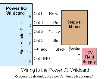
For optimal efficiency, set MAX_STEPPERS to the number of stepper motors being controlled, with a maximum limit of four. Motors are identified by indices 0, 1, 2, and 3. On the QCard, there is a trade-off between the number...

The project involves designing and constructing a breadboard power supply that draws power from an ATX-like switch-mode power supply (SMPS) using a 4-pin Molex connector. The design features a switch to select either a 12V or 5V output. However,...

Pulse position modulation is similar to pulse width modulation, but the frequency is not constant. Like pulse width modulator circuit, pulse position modulation... Pulse Position Modulation (PPM) is a modulation technique in which the position of a pulse within a...

A very simple dimmer circuit with only the essentials. In this circuit, the values are given for a BT138 at 220V AC. For 115V AC, experimentation with values may be necessary. R1 can vary from one triac to another;...
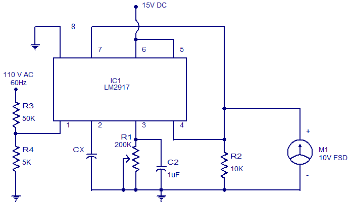
The circuit diagram of a simple capacitance meter using IC LM2917 is illustrated. The LM2917 is a high-gain monolithic frequency-to-voltage converter IC from National Semiconductors. While the primary application of the LM2917 is in tachometers, it can also be...
The LM386 is a widely recognized and effective option for various designs that necessitate a compact audio power amplifier (1-watt) integrated into a single chip. However, the LM386 requires... The LM386 is a low-voltage audio power amplifier that is commonly...