
Pulse Position Modulator Using 555 IC
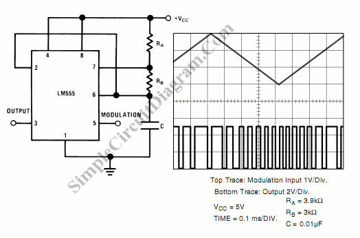
Pulse Position Modulation (PPM) is a modulation technique in which the position of a pulse within a fixed time frame is varied according to the amplitude of the input signal. Unlike Pulse Width Modulation (PWM), where the width of the pulse changes while the frequency remains constant, PPM alters the timing of the pulse, thereby allowing for a more efficient transmission of data over a communication channel.
In a PPM system, each pulse represents a sample of the modulating signal, with the time interval between successive pulses being directly proportional to the amplitude of that signal. This method allows for a more robust signal against noise and interference, as the timing of the pulses can be more easily synchronized at the receiver end.
The basic components of a PPM circuit include a signal generator, a pulse generator, and a timing circuit. The signal generator produces the modulating signal, which is then processed by the pulse generator to create the PPM signal. The timing circuit ensures that pulses are spaced correctly according to the desired modulation scheme.
PPM is widely used in applications such as optical communications, remote control systems, and digital data transmission, where high noise immunity and efficient bandwidth usage are critical. By varying the position of the pulse rather than its width, PPM can achieve higher data rates and improved performance in environments with significant interference.Pulse position modulation is similar to pulse width modulation, but the frequency is not constant. Like pulse width modulator circuit, pulse position.. 🔗 External reference
Related Circuits
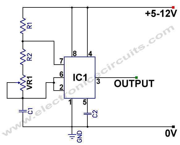
555 Variable Frequency Square Wave Generator. This simple 555 Variable Frequency Square Wave Generator produces a variable frequency output. The 555 Variable Frequency Square Wave Generator is a versatile circuit that utilizes the 555 timer IC to generate square wave...
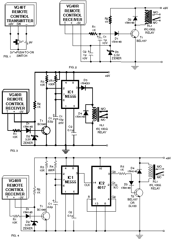
Remote control utilizing VHF modules. Several designs for remote control switches using the VG40T and VG40R remote control pair are presented here. The miniature transmitter module illustrated in Fig. 1. The VG40T and VG40R are VHF radio frequency (RF) modules...
The TDA3567 is a monolithic integrated decoder designed for the NTSC color television standards. It incorporates all the necessary functions for the demodulation of NTSC signals. Additionally, it features a luminance amplifier and an RGB matrix amplifier. These amplifiers...
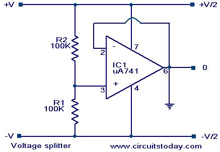
Voltage splitter using op-amp uA741 IC, circuit diagram, working, description. The voltage splitter circuit utilizing the uA741 operational amplifier (op-amp) is designed to provide a stable output voltage that is a fraction of the input voltage. The uA741 is a...
The circuit is designed to provide a reminder for lights using a monostable delay configuration. It comprises a monostable delay circuit, a driving circuit, a buzzer, light-emitting diodes (LEDs), and other components. The output signal from the delay circuit,...
The count advances as the clock input transitions to high (on the rising edge). Each output from Q0 to Q9 activates sequentially as the counting progresses. For specific functions, such as flash sequences, outputs may be combined using diodes....