
ir receiver circuit

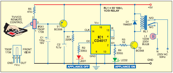
The IR receiver circuit typically comprises several key components, including a photodiode or phototransistor, a resistor, an LED, and a power supply. The photodiode or phototransistor serves as the primary sensor, converting the incoming infrared light pulses from the transmitter into an electrical signal. When the IR LED emits a 38 kHz modulated signal, the photodiode detects this signal and generates a corresponding output.
The circuit's simplicity is one of its main advantages, making it suitable for educational purposes or basic remote control applications. The resistor is often used to limit the current flowing through the photodiode or phototransistor, ensuring its safe operation. The LED serves as an indicator, visually demonstrating the detection of the IR signal.
In terms of configuration, the photodiode or phototransistor is connected to the power supply, and its output is linked to the LED. When the IR signal is received, the circuit allows current to flow through the LED, causing it to blink as an indicator of successful signal reception. The design can be further enhanced by incorporating additional components such as amplifiers or filters, depending on the specific application requirements.
Overall, this IR receiver circuit is an effective and efficient solution for applications requiring basic infrared signal detection, providing a clear visual indication of signal reception through the blinking LED.This is a very simple and easy to make IR receiver circuit. This infrared receiver circuit is using only few components and it is able to receive 38KHz carrier signal. The working of this circuit is simple when ever the IR LED receive any signal from 38KHz transmitter it will blink LED in the circuit.
🔗 External reference
Related Circuits
It is essential to consider migrating to PIC microcontrollers and exploring compilers such as those offered by Proton Smart, which include Sony IR and Philips RC5 codecs. This approach is particularly advisable for security-sensitive applications. Additionally, Bluetooth and Wi-Fi...
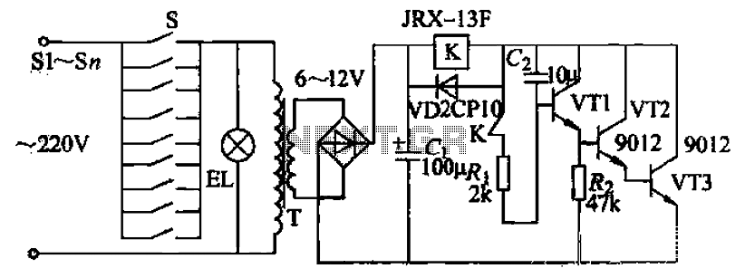
Pressing the button switch Sl-Sn activates the circuit, turning on the transformer T. The low-voltage alternating current from the secondary winding is directed to a bridge rectifier and a filter capacitor Ci, which produces a DC voltage. This voltage...
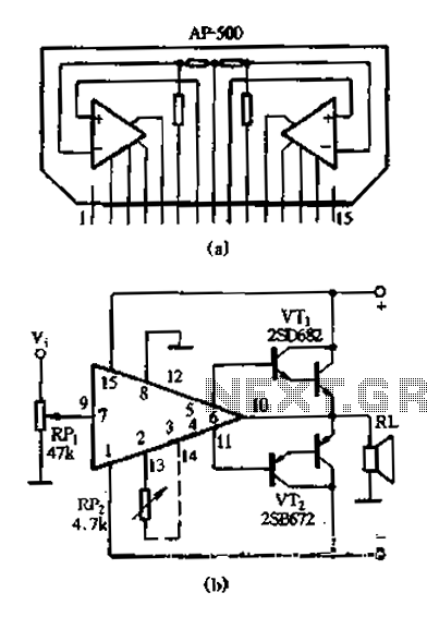
The AP500 is a high-performance dual-channel FET DC amplifier driver module designed for high operating voltage applications. It features push power, low distortion, a wide frequency response, and a simple external circuit. Utilizing superior resistance characteristics in audio circuits,...
Designed for communications use, this equalizer circuit utilizes a Mitsubishi M5226P audio equalizer IC to modify frequency response. It operates with a supply voltage ranging from 9 to 20 V. Capacitors C6 through C16 are polyester film capacitors with...
This simple alarm timer circuit is constructed using a 4060 IC, which features an integrated oscillator known for its good stability and relatively wide frequency range. The 4060 integrated circuit (IC) serves as the core component of this alarm timer...
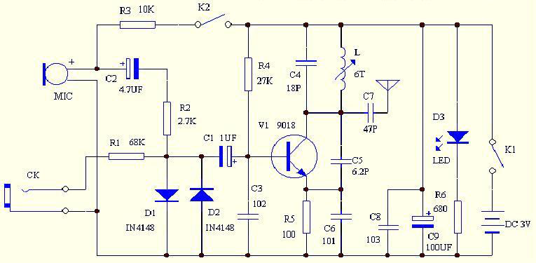
The circuit enables FM radio reception frequency adjustment by modifying the inductance value (L) of the coil (La) through stretching or compressing it, allowing for easy alteration of the transmission frequency to avoid interference with FM radio signals. The...