
FM radio receiver

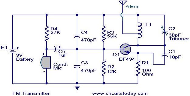
The described circuit employs a variable inductor, which is crucial for fine-tuning the transmission frequency within the FM band. The inductance (L) can be adjusted mechanically or electronically, depending on the design of the coil (La). This adjustment allows the user to shift the frequency of the transmitted signal, ensuring it remains clear of existing FM radio frequencies, thus preventing interference.
The coupling of the transmitted signal to the antenna is achieved through capacitor C4. This capacitor serves multiple purposes: it blocks any DC component of the signal, allowing only the AC signal to pass through, and it also helps in impedance matching between the transmitter circuit and the antenna. Proper impedance matching is essential for maximizing power transfer and ensuring efficient radiation of the transmitted signal.
In a practical implementation, the circuit may include additional components such as resistors and diodes for signal conditioning, as well as a power supply circuit to provide the necessary voltage and current levels for operation. The design might also incorporate feedback mechanisms to stabilize the output frequency against variations caused by temperature changes or component aging.
This circuit configuration is commonly found in low-power FM transmitters, where the flexibility to adjust the transmission frequency is vital for compliance with regulatory standards and to avoid interference with licensed FM broadcasters. Careful attention to component selection and layout is essential to minimize unwanted noise and ensure a clean transmission.Covering FM radio reception frequency, by adjusting the L value (La stretch or compression coil L) can easily change the transmission frequency to avoid the FM radio. Transmit signal coupled to the antenna through C4 to launch out. 🔗 External reference
Related Circuits
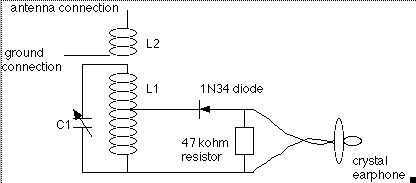
The coil on the left is coil #1, and has 17 taps. The other coil is coil #3. The vertical strips are the lath material, screwed to the 1 foot long base. Holes drilled in the ends of the...
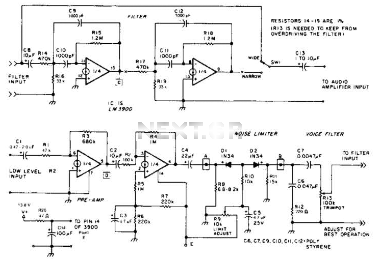
The noise limiter circuit features a preamplifier clipper and a switchable audio bandpass filter. Audio levels ranging from 5 to 50 mV are amplified in a preamplifier to several volts peak-to-peak, which are then sent to a clipper and...
The game was originally designed to position three balls locked in holes on a slowly rotating ring around the Deadworld. Once the third ball was secured, a mechanical arm would release them, dropping the balls onto the playfield. This...
The MK484 AM receiver circuit is a simple design based on the MK484 AM receiver IC from Rapid Electronics Ltd. The MK484 is a monolithic integrated circuit that incorporates all necessary sections of an AM receiver, including an RF...
The following circuit illustrates the RF block diagram of a GPS receiver. This circuit is based on the MAX2742 integrated circuit. Features include a complete GPS receiver functionality. The GPS receiver RF block diagram utilizing the MAX2742 IC encompasses several...
Many later radios utilize four 7-pin valves and require a high tension (HT) supply of 90V at approximately 12mA, and a low tension (LT) supply of either 125mA or 250mA, depending on the specific valves used. The original batteries...