
Ir Reflection Proximity Switch

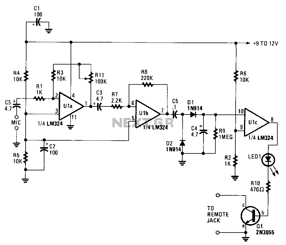
The circuit described involves an infrared (IR) transmission and reception system utilizing LEDs and phototransistors to facilitate communication or detection applications. The system operates by generating IR radiation through LED2, which is modulated at a frequency of 1 kHz. Ul serves as a switching mechanism that controls the activation of LED2, allowing for intermittent transmission of the IR signal.
Upon transmission, the IR radiation emitted by LED2 travels through the environment and can be reflected by nearby objects. This reflected IR energy is then detected by phototransistor Q3, which converts the optical signal back into an electrical signal. The output from Q3 is an audio signal that corresponds to the characteristics of the received IR radiation.
To enhance the signal strength and ensure reliable communication, the audio signal from Q3 is amplified by transistor Q2. This amplification stage is crucial for improving the signal-to-noise ratio before the signal is processed further. The amplified signal is subsequently sent to a decoder, which interprets the signal for further action or processing.
Additionally, LED1 serves as an indicator light, illuminating when reflected IR is detected, providing a visual confirmation of the system's operation. The design may incorporate an isolator at the input of LED1, facilitating the control of a triac or silicon-controlled rectifier (SCR). This feature allows the circuit to interface with higher power devices or loads, enabling the control of various electrical systems based on the presence of reflected IR signals. Overall, this circuit exemplifies a practical application of IR technology in sensing and control systems. IR radiation from LED2 (modulated by a 1-kHz wave) is keyed by Ul, and Ql is radiated. Reflected IR energy i s picked up by Q3, and the audio signal from Q3 is amplified by Q2 and sent to the decoder. The LED1 lights to indicate presence of reflected IR. LED1 can be the input of an isolator so that a triac or SCR can be controlled.
Related Circuits
This circuit can cause a cassette recorder to automatically turn on and record when a sound or noise is present. Another use is when the sound-activated switch is used to turn on a cassette player, allowing it to function...
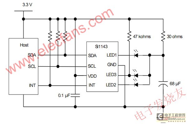
The electronic device detects proximity, measuring the user's distance quickly. Currently, most proximity sensors available on the market have a relatively short detection range of approximately 1 to 10 cm. The use of infrared LEDs in multipulse mode for...
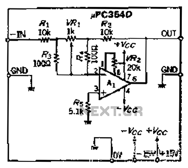
The loop gain of the operational amplifier (OP) is primarily influenced by the ratio of the input resistor to the feedback resistor. Consequently, any resistance error can lead to a corresponding gain error, which necessitates the use of high-precision...
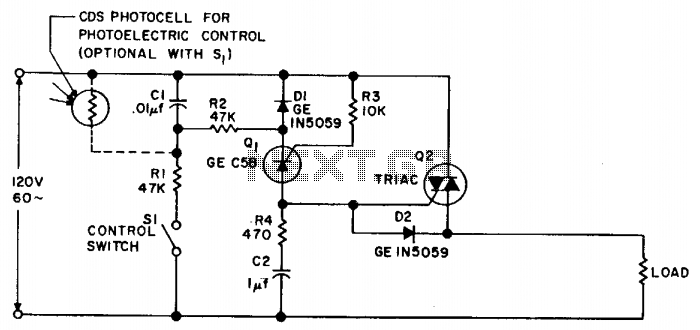
Synchronous switching activates only when the AC supply voltage crosses zero and deactivates only when the current reaches zero. This circuit responds to either a mechanical switch or a variable resistance, such as a cadmium-sulfide photocell. It minimizes disturbances...
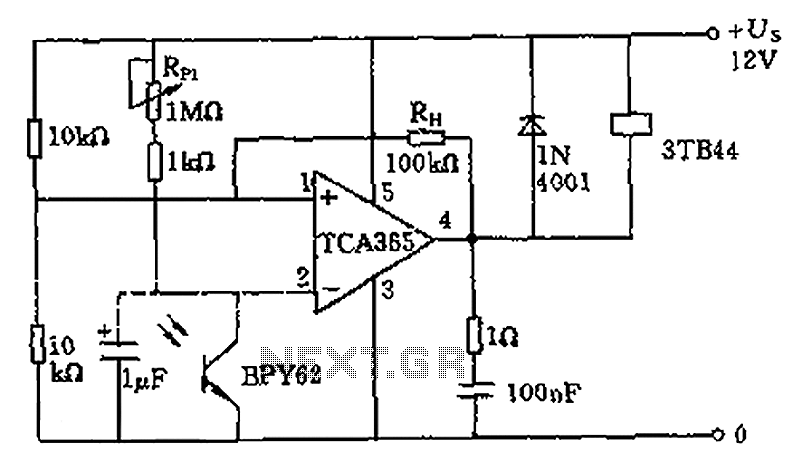
A bridge input circuit utilizing a phototransistor BPY62 and a power operational amplifier is capable of controlling power loads up to 8.5 kW. It features a voltage divider composed of two 10 kΩ resistors, creating a midpoint connection. The...
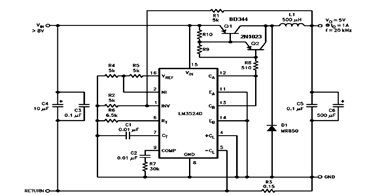
The schematic diagram below illustrates a 5V/1A Step-Down Switching Regulator utilizing the LM2524D Regulating Pulse Width Modulator (PWM). Additional parameters, PC board layout, stuffing diagram, and more information can be found in the LM2524D datasheet. The circuit design features the...