
Super lock circuit diagram

The circuit design features the CD4017 decade counter, which is capable of counting from 0 to 9, with each output terminal representing a specific count. In this application, the outputs are utilized to manage the locking mechanism based on the input of a specific password. When a valid password is entered through the input switching circuit, the corresponding output of the CD4017 is activated, allowing it to trigger a relay or another locking mechanism.
In terms of implementation, the circuit requires a power supply compatible with the operating voltage of the CD4017, typically between 3V to 15V. The password input switching circuit can be constructed using a matrix of push buttons, where each button corresponds to a digit in the password. The use of diodes in the matrix is critical to prevent ghosting and ensure that only the intended button press is registered.
The ancillary components may include resistors for pull-down configurations, capacitors for debouncing the switches, and possibly a microcontroller for additional functionality such as password management or logging attempts. The inclusion of a display, such as a 7-segment display, can provide visual feedback to the user, indicating whether the entered password is correct or incorrect.
Overall, this lock circuit design not only emphasizes security through a high number of password combinations but also maintains simplicity in its construction, making it suitable for various applications where enhanced security is required. As shown in the lock circuit by a decimal counter CD4017 composed by ten its output terminal is connected through a combination of the number of passwords the group consisting of up to 100 million group, can be called super-lock, which circuit is shown in shown. Circuit relatively simple, consisting of a CD4017 and 10 password input switching circuit related and ancillary components.
Related Circuits
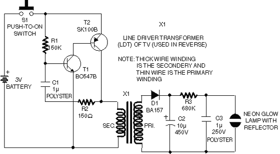
This circuit operates on 12V DC instead of mains AC. This is an advantageous approach for those who prefer not to deal with circuits connected directly to mains voltage or wish to power the stroboscope using batteries. Flash Slave...
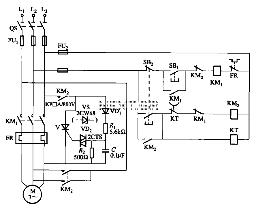
The circuit illustrated in Figure 3-148 eliminates the requirement for a step-down transformer by utilizing a thyristor for brake control in small capacity asynchronous motor braking applications. Upon shutdown, the contactor KM1 releases, while contactor KM2 engages the brake...
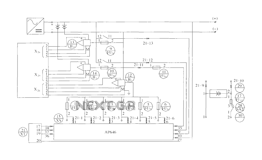
The components include B2 (13) and B3 (14) designated for the Hall current sensor; FU9 (9) and FU10 (10) serve as fuses; an AP646 alarm signal is connected to the fuse board; terminals X24, X26, and X29 function as...
The LM317 is an adjustable, positive 3-terminal voltage regulator capable of supplying 100 mA (for RA87U control) or 1.5 A (for Order Code UF27E and N61CA) across an output voltage range of 1.2 V to 37 V. These voltage...
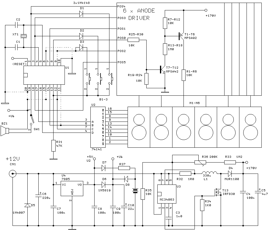
The clock will have 6 digits and time setting will be done by means of a few buttons. I will try to use the most common types from widely used microcontroller families of miscellaneous producers. I will write the...
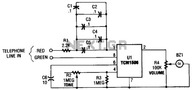
The circuit utilizes the TCM1506 ring detector/driver integrated circuit, which is a monolithic IC designed to replace mechanical bells in telephones. It is powered and activated by the telephone line's ringing signal, which ranges from 40 to 150 V...