
IR Remote Control Extender mark 4 Circuit

The infrared wired repeater circuit serves as an interface for controlling various electrical appliances from a distance, utilizing infrared signals for communication. This circuit typically consists of several key components, including resistors, an infrared receiver, an infrared transmitter, and possibly additional supporting components like capacitors and diodes.
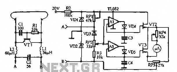
The resistors listed in the parts list, R1 (1kΩ), R2 (3.3kΩ), and R3 (10kΩ), are used to limit current and set the appropriate voltage levels within the circuit. R1 might be used in conjunction with the infrared receiver to ensure that the input signal is at a safe level for processing. R2 could serve as a pull-up resistor for the output signal, ensuring that the line is high when the infrared signal is not being received. R3 may be part of a voltage divider or biasing network for the infrared transmitter, allowing it to function efficiently when sending signals to the controlled appliances.
The infrared receiver detects signals from a remote control device, converting these signals into electrical impulses. The output from the receiver is then processed by the circuit, which may include a microcontroller or a simple transistor switch to activate the infrared transmitter. The transmitter, in turn, sends the appropriate infrared signals to the targeted appliances, effectively allowing remote control functionality.
To enhance the circuit's performance, additional components such as capacitors may be included to filter out noise and stabilize the power supply. Diodes could be used for protection against reverse polarity or to ensure that current flows in the correct direction.
Overall, this infrared wired repeater circuit is a practical solution for remote appliance control, providing convenience and flexibility in managing electronic devices from various locations within a home or office environment.An Infra Red wired Repeater circuit to control appliances from a remote location. Parts List: R1: 1k Resistor (1) R2: 3.3k Resistor (1) R3: 10k. 🔗 External reference
Related Circuits
Similar to the CMOS-based touch switch available on this site, this transistor-based touch switch can activate a load simply by the user touching a metal plate. It is designed to directly switch a relay, allowing it to be used...
The development of the entire system necessitated a thorough identification of all processes related to the laser controller. The initial diagram outlines the primary physical components utilized in the CNC laser system. The setup includes a power supply, a...
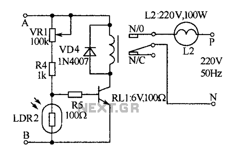
The receiver, as depicted in the figure, assists patients in avoiding missed audio signals during the daytime. The receiver operates independently, and the lighting will automatically turn off. At night, the lighting signal receiver activates simultaneously with the patient's...
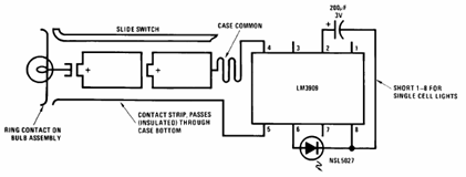
The schematic presented below illustrates the Flashlight Finder circuit diagram utilizing the LM3909, a monolithic oscillator specifically designed for flashing Light Emitting Diodes (LEDs). The Flashlight Finder circuit employs the LM3909 integrated circuit, which is capable of generating a series...
The soil moisture meter circuit is useful for monitoring the moisture levels in plants. It is a simple and effective circuit. The soil moisture meter circuit is designed to measure the volumetric water content in soil, providing valuable data for...

A compact audio amplifier circuit utilizing the TDA 7052 integrated circuit from Philips. This circuit is suitable for use as a pocket radio amplifier, delivering an output power of 2 watts. The TDA 7052 is a low-voltage audio amplifier designed...